ACF5000 FTIR ANALYZER SYSTEM | OI/ACF5000-EN REV. A 73
Overview
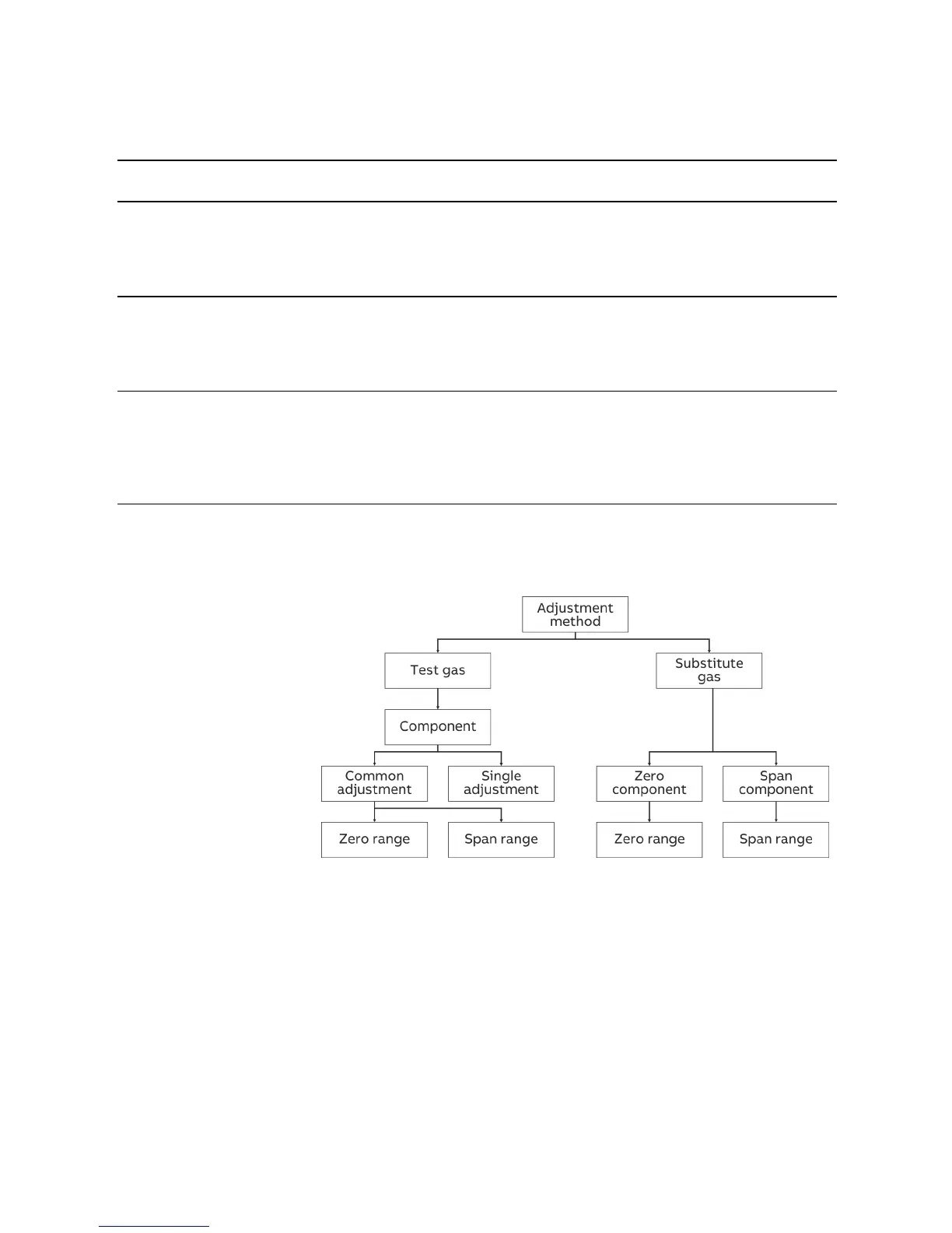
The following table presents the adjustment methods at a glance.
Qty. Adjustment
MC MR method To be configured … To be adjusted … The adjustment affects …
1 1 Test gas/Single the zero point and the
end point in every meas-
uring range individually
for every measured
component
only on the relevant
measuring range
≥ 1 > 1 Test gas/Common the measuring ranges
for zero point and
end point adjustment
the zero point in a meas-
uring range and the end
point in another measur-
ing range for every
measured component
on all measuring ranges of
the relevant measured
component
> 1 ≥ 1 Substitute gas the components and
measuring ranges for
zero point and end
point adjustment
the zero point in a meas-
uring range of a compo-
nent and the end point in
a measuring range of
another component every
detector
on all components and
measuring ranges of the
relevant detector
MC = measuring and substitute gas components
MR = measuring ranges per component
Setting the adjustment method
The adjustment method can be set separately for every one of the three
types of controlling the adjustment (manual, automatic and externally con-
trolled).
The measuring ranges for the zero point and end point adjustment for
common and substitute gas adjustment are set jointly for all three types of
controls.
For the substitute gas adjustment, the components need to be additionally
set for the zero point and end point adjustment.