32 ANSI MEDIUM VOLTAGE METAL-CLAD DIGITAL SWITCHGEAR
Logic zone selective interlocking
When used in protection schemes, logic zone
selective interlocking scheme selectively trips the
circuit breaker according to the logic scheme. The
start signal of the Overcurrent or ground fault
protection is sent from the Outgoing feeders to
the upstream circuit breaker, such as the Incomer,
Generator and Bus tie, to block upstream
Overcurrent or Ground fault protection. For
safety reasons, the Logic zone selective
interlocking scheme can only be used with Circuit
breaker failure protection.
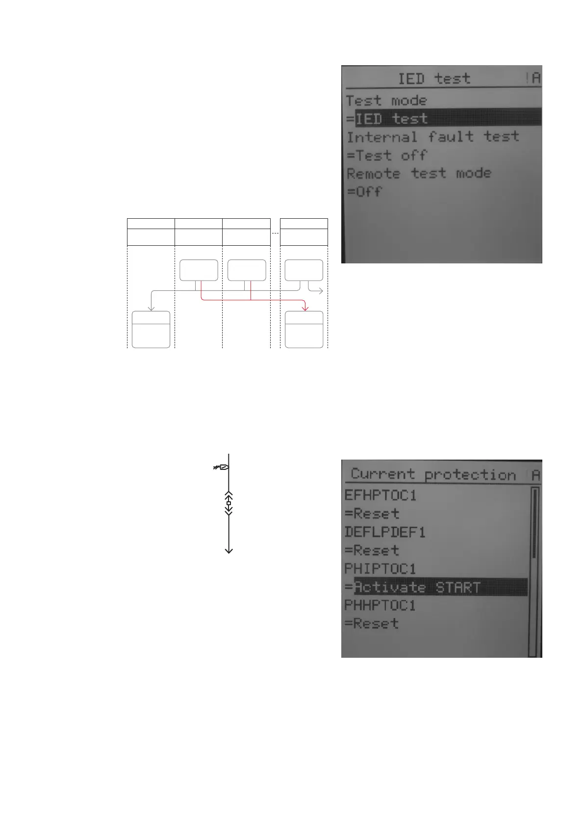
• Step 3/10
On the protection relay LHMI (tested feeder) go
to -> Main Menu/Test/IED test
- Test mode = IED test
- The ready LED is flashing when the protection
relay is in the test mode.
• Step 4/10
On the protection relay LHMI (tested feeder) go
to -> Main Menu/Test/Function tests/
Current protection
- PHIPTOC1 = Activate START
• Step 1/10
Move all circuit breaker trucks into the service
position in the relative section. Check all the
circuit breakers status on the protection relay
LHMIs.
IA=0A
IB=0A
IC=0A
IG=0.0A
VAB=0.00kV
VBC=0.00kV
VCA=0.00kV
3P=0kW
3Q=0kVAr
—
61
• Step 2/10
On the protection relay LHMI (upstream circuit
breaker such as the Incomer, Generator and Bus
tie receiving LBBP blocking signal) go to -> Main
Menu/Test/IED test
- Test mode = IED test
- The ready LED is flashing when the protection
relay is in the test mode.
—
60 Logic scheme of the
Logic busbar protection
—
61 Single line diagram,
the circuit breaker is in
the service position
—
62 Entering test mode
—
63 Activating
START signal
—
60
—
62
—
63
A01
Incoming feeder Motor feeder
Transformer
feeder
Bus tie
50-OC
inst. start
50-OC
inst. start
50-OC
inst. start
OR OR
Block 50-OC
inst
Block 50-OC
inst
A02 A03 AB1 2 3 10