98 AO2000 CONTINUOUS GAS ANALYZERS | OI/AO2000-EN REV. B
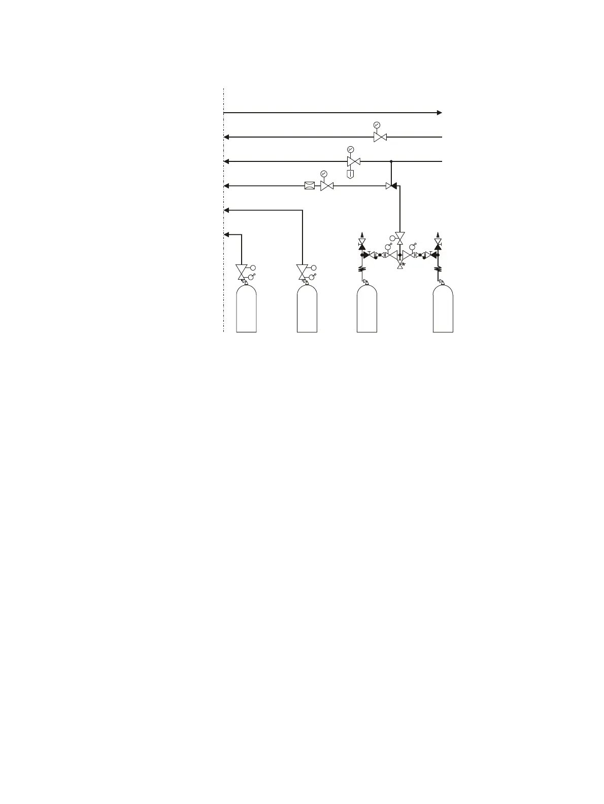
Connection of process gases and test gases
H
2
H
2
N
2
CH /N
nm 2
Switch-over station
with safety valve
Instrument air
p = 4000 ± 500 hPa
e
Span gas
p = 1000 ± 100 hPa
e
Zero gas
Combustion gas
p = 1200 ± 100 hPa
e
Exhaust gas
Pneumatic
shut-off valve
Combustion air
p = 1200 ± 100 hPa
e
Flow
restrictor
34
33
36
38
37
35
The numbering of the gas connections corresponds to the numbering in the
connection diagram (see page 83) as well as the labeling on the rear of the
analyzer module.
Instrument air connection
Instrument air is used as propellant for the air jet injector and as purging air
for the housing purge (see page 40).
Connect (see page 83) the instrument air line to the instrument air inlet of
the analyzer module via a pressure regulator (0 to 6 bar).
Combustion air connection
Connect (see page 83) the combustion air line to the combustion air inlet of
the analyzer module via a pressure regulator (0 to 1.6 bar).
Combustion gas connection
See section "Fidas24: Connecting the combustion gas line" (see page 100)
Test gas connection
The test gas outlet is connected to the sample gas connection ex works.
If the test gases are to be introduced directly into the gas sampling point,
the connection between the test gas outlet and the test gas inlet on the
sample gas connection must be removed, and the respective opening in the
sample gas connection must be sealed with an M6 screw, so that it is
gas-tight.