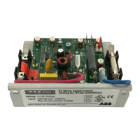
This document describes the Baldor BC141, BC142, BC142-5, and BC142-6 full-wave variable speed DC motor controls, which are part of the ABB Group. These controls are designed for reliability and performance at an affordable price, featuring Surface Mount (SMT) construction.
Function Description:
The Baldor BC141, BC142, BC142-5, and BC142-6 are variable speed DC motor controls. They provide precise control over DC motors, allowing for adjustable speed, acceleration, and deceleration. The controls incorporate a patented super-fast Direct-Fed™ current limit circuit for protection against direct shorts to the SCR power bridge. They are equipped with high-surge, 25 Amp SCRs, and AC line and armature fusing for enhanced reliability. A key feature is the exclusive Plug-In Horsepower Resistor® system, which eliminates the need for recalibrating IR Compensation and Current Limit when using different horsepower motors. The controls can operate in a voltage following mode by accepting an isolated analog input signal.
Important Technical Specifications:
- Input Voltage (VAC):
- BC141: 115 VAC
- BC142: 208/230 VAC
- BC142-5 & BC142-6: 115 VAC or 208/230 VAC (selectable via Jumper J1)
- Motor Voltage (VDC):
- 0-90 VDC (for 115 VAC input)
- 0-180 VDC (for 208/230 VAC input)
- BC142, BC142-5, BC142-6 can operate 90 VDC motors on 208/230 VAC input (step-down operation).
- Horsepower Rating:
- Can be extended to 1.5 HP for 90 VDC output and 3 HP for 180 VDC output with an Auxiliary Heat Sink.
- AC Line Current (Max Load):
- BC141 (115V): 8 Amps (0-90VDC, 0.75 HP)
- BC142 (230V): 6 Amps (0-180VDC, 1.5 HP)
- BC142-5 (230V): 6 Amps (0-180VDC, 1.5 HP)
- BC142-6 (230V): 8 Amps (0-90VDC, 0.75 HP)
- Armature Fuse Rating: Varies by motor HP and voltage, ranging from 0.5 Amps to 25 Amps.
- Field Voltage (Shunt Wound Motors Only): 50 VDC, 100 VDC, or 200 VDC depending on input and armature voltage.
- Speed Range (Ratio): 50:1
- Armature Feedback Load Regulation (0 - Full Load, 50:1 Speed Range): 1%
- Tachometer Feedback Load Regulation (0 - Full Load, 50:1 Speed Range): 1%
- Line Voltage Regulation (at Full Load, ± 10% Line Variation): 0.5%
- Control Linearity (% Speed vs. Dial Rotation): 2
- Acceleration (ACCEL) Trimpot Range: 0.2 – 10 seconds (Factory Setting: 2)
- Deceleration (DECEL) Trimpot Range: 0.2 – 10 seconds (Factory Setting: 2)
- Maximum Speed (MAX) Trimpot Range (% Base Speed): 50 – 110 (Factory Setting: 100)
- Minimum Speed (MIN) Trimpot Range (% Base Speed): 0 – 30 (Factory Setting: 0)
- Current Limit (CL) Trimpot Range (% Full Load): 0 – 200 (Factory Setting: 150)
- IR Compensation (IR) Trimpot Range (at Specified Full Load @ 90, 180 Volts DC Output): 0 – 24, 48 (Factory Setting: 3, 6)
- Maximum Operating Ambient Temperature: 40 °C / 104 °F
- Dimensions: Compact size (4.30 X 3.64 X 1.25 inches).
- Approvals: UL Listed (USA and Canada) and CE Approved.
Usage Features:
- Versatile Feedback: Selectable armature or tachometer feedback for precise speed control.
- Adjustable Trimpots: Includes trimpots for minimum speed, maximum speed, current limit, IR compensation, and linear acceleration and deceleration, allowing fine-tuning for specific applications.
- Auto-Inhibit®: Eliminates surging during rapid AC line switching, ensuring smooth operation.
- Pulse Transformer Triggering: Provides cogless operation at low speeds.
- Superior Noise Rejection: Circuitry designed to eliminate false starts and blown SCRs.
- Electronic Switching: Enable (normally closed) and Inhibit (normally open) functions provide electronic control of the output.
- Main Speed Potentiometer: Supplied with a 5 kΩ potentiometer for speed control.
- Voltage Following Mode: Can be controlled by an isolated 0-9 Volt DC analog input signal.
- Mounting: Recommended to be mounted on a flat surface with adequate ventilation. If an optional Auxiliary Heat Sink is used, ensure unrestricted airflow.
- AC Line Connection: Connects to L1 (Line Fuse) and L2. For 115VAC, neutral connects to L2.
- Motor Connection:
- Permanent Magnet (PM) Motors: Connect positive lead to A+ (Armature Fuse*) and negative lead to A-. Jumper J2 must be set to the corresponding motor voltage.
- Shunt Wound Motors: Connect field positive to F+ and negative to F-. For half voltage field (50 VDC with 100 VDC rated armature), use L1 and F+.
- Plug-In Horsepower Resistor®: Simplifies calibration of IR Compensation and Current Limit for various motor horsepowers and voltages.
- Armature Fuse: Provides overload protection for the motor and control.
- Remote Speed Potentiometer: Allows connection of an external potentiometer for speed control.
- Enable Circuit: A switch or contact wired to CONN1 can start and stop the motor, accelerating to the Main Speed Potentiometer setting when closed and decelerating to stop when opened.
- Inhibit Circuit: A switch or contact wired to Terminals I1 and I2 can stop the motor (coast to stop) when closed and allow it to accelerate to the Main Speed Potentiometer setting when opened.
- DC Tachometer Connection: A DC tachometer can be used for 1% load regulation of set speed. Jumper J2 must be set to the T position. Supports 7 Volt or 50 Volt per 1000 RPM DC tachometers.
- Armature Switching and Dynamic Braking: Allows for controlled braking by disconnecting the armature and dissipating motor voltage through a brake resistor (RB), activated simultaneously with the Inhibit Circuit.
Maintenance Features:
- Troubleshooting Guide: The manual includes a comprehensive troubleshooting guide with common symptoms, possible causes, and suggested corrective actions for issues like motor not running, motor hums, erratic performance, and incorrect rotation direction.
- Fuse Replacement: The AC line fuse (25 Amp, factory installed) protects against catastrophic failure. Armature fuses are also recommended and can be replaced.
- LED Indicators: Power ON (PWR ON) LED indicates AC power is applied. Pilot Light indicates the control is running. Current Limit (CL) LED illuminates when the motor is overloaded.
- Regular Checks: The startup procedure includes verifying line voltage, voltage select switch setting, armature fuse and Plug-In Horsepower Resistor® installation, and motor rotation direction.
- Calibration: Trimpots for MIN, MAX, ACCEL, DECEL, Current Limit, and IR Compensation can be recalibrated as needed.
- Optional Accessories:
- Auxiliary Heat Sink (BC143): Doubles the horsepower rating.
- Barrier Terminal Board (BC147): Converts quick-connect terminals to barrier terminals, includes prewired AC line and armature fuse holders.
- Signal Isolator (BC152): Provides isolation between non-isolated signals and the control, useful for process controllers and microprocessors.
- Signal Isolator (BC145): For multiple follower motors controlled by a single leader motor or Main Speed Potentiometer.
- Dial Plate and Knob Kit (BC149): Provides indication of the Main Speed Potentiometer position.
- DIN Rail Mounting Kit (BC218).
- RFI Filter (BC24-1F): Provides RFI and EMI suppression.
Safety Notices:
- High voltages (up to 1000 volts) are present; only qualified personnel should perform installation and troubleshooting.
- Ensure proper grounding before applying power.
- Disconnect all power before working on the equipment.
- Do not use in explosive environments.
- Automatic startup features (when Enable jumper is installed, or after power restoration/fault reset) require user awareness and appropriate alarms to prevent injury or damage.
- Do not use start/stop, inhibit, or enable functions as safety disconnects; use an AC line disconnect.
- Disconnect motor leads before performing a Dielectric Withstand test on the motor.
- Do not connect AC power to motor terminals A1 and A2.
- Avoid using Grounded Leg Delta transformer power leads; a four-wire Wye is recommended.
- Ensure the circuit can deliver not more than 5,000 RMS symmetrical short circuit amperes.
- Adjusting current limit above 150% of motor nameplate rating can cause overheating and demagnetization.
- Do not leave the motor in a locked rotor condition for more than a few seconds.
- Shunt wound motors may be damaged if field windings remain energized without armature rotation.
- If adjusting trim pots with power applied, use an insulated adjustment tool and safety glasses.