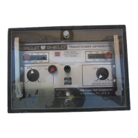
The ABB Circuit-Shield™ Type 87T is a high-speed differential protection relay designed for power transformers. It is a single-phase relay, with a set of three relays required for the protection of one power transformer. The relay is available in models for the protection of two-winding and three-winding transformers.
Function Description:
The Type 87T relay provides differential protection for power transformers. It features a linear percentage differential characteristic to accommodate CT ratio mismatch, the operation of on-load tap changers, and CT errors during high fault currents external to the protected zone. Controls on the front panel allow adjustment of the slope (15-40%) and the minimum operate current. A second-harmonic restraint unit prevents relay operation due to transformer magnetizing inrush current. This unit is factory calibrated to restrain on 15% second harmonic content, but can be adjusted if required. An unrestrained instantaneous unit is also included, operating on the magnitude of the difference current to back up the percentage differential unit. This instantaneous unit is factory set at 10x tap, but is adjustable (8-20x) in the field. The relay incorporates ratio correcting taps, eliminating the usual need for external auxiliary CTs. The high continuous rating of each tap offers greater flexibility in tap selection, and the relay's low burden improves CT performance.
Important Technical Specifications:
- Ratio Matching Taps: See Table 1 for specific tap ratios.
- Continuous Rating: 1st second rating: 200 Amperes, any tap. Burden: See Table 3.
- Percentage Restraint Element:
- Minimum operate current: Adjustable 13-65% of tap setting.
- Slope: Adjustable 15-40%.
- Refer to Figures 6 and 7.
- Instantaneous Element:
- Internally adjustable 8-20x tap.
- Factory set at 10x tap.
- Harmonic Restraint Element:
- Restrain on 2nd harmonic.
- Internally adjustable approximately 10%-20%.
- Factory setting: 15%.
- Operating Time: See Figure 5.
- Output Contact Rating:
- 125VDC: 30A closing/tripping, 5A continuous, 0.3A break.
- 250VDC: 30A closing/tripping, 5A continuous, 0.1A break.
- Operating Temperature Range: -20 to +70°C.
- Control Voltage (models available for):
- 125VDC @ 0.05A max. drain (allowable range 100-140VDC)
- 125VDC @ 0.05A max. drain (allowable range 88-125VDC)
- 250VDC @ 0.05A max. drain (allowable range 200-280VDC)
- 220VDC @ 0.05A max. drain (allowable range 176-250VDC)
- 48VDC @ 0.05A max. drain (allowable range 38-56VDC)
- 32VDC and 24VDC: See note 2 below, and page 22.
- Dimensions: 6.88 inches (175 mm) wide, 8.38 inches (213 mm) high, 6.56 inches (167 mm) deep (panel). Panel cutout: 5.6 inches wide, 3.19 inches (81.0 mm) high.
- Burden Data: See Table 3 for tap setting, ohms, and P.F. values.
Usage Features:
- Installation: The relay is designed for easy installation, with mounting and panel drilling instructions provided.
- Settings Calculation: A detailed procedure for calculating relay settings for specific applications is outlined, including steps for determining maximum load currents, maximum through-fault currents, CT ratio selection, CT secondary currents, relay currents, ratio of relay currents, percentage differential mismatch, instantaneous unit setting, and minimum operating current.
- Test Procedures: The manual provides comprehensive testing procedures for various relay characteristics:
- Built-in Test Function: A built-in test circuit is provided for convenience in running a test on the relay and associated trip circuits. The test button is labeled "TRIP," and depressing the button will cause an immediate trip.
- Minimum Operating Current and % Differential Tests: Connect the relay to a test circuit (Figure 8) and apply control voltage. Set the relay's rating as marked on the front panel. Select and make settings from the listing in Table 5.
- Instantaneous Unit Tests: Typical test connections are shown in Figure 10. If two sources are required in parallel to obtain needed current levels, connect as shown by dotted lines.
- Harmonic Restraint Tests: Source is 60Hz for 60Hz units, 50Hz for 50Hz rated units. Typical test connections are shown in Figure 11.
- Three-Winding Relays: Specific instructions for testing when a 3 winding relay is being tested, noting that the differential characteristic test should be repeated so that the third phase is also tested.
- DC/DC Inverter (Type 96): For systems using 24VDC or 32VDC control voltage, the Type 96 Inverter is available. One inverter is used for each Type 87T. Specify the Type 87T with 48VDC control rating.
Maintenance Features:
- Routine Maintenance: No routine maintenance is required on these ABB Circuit-Shield™ solid-state relays. However, periodic verification (annually) that the relay is in proper working order is recommended. If a non-operative relay is returned to the factory for repair, a schematic diagram is available on request. Renewal parts will be quoted on request.
- Drawout Units: The drawout circuit boards are interchangeable. A unit is identified by the catalog number stamped on the front panel and by a serial number stamped on the bottom side of the drawout circuit board. The board is removed using the metal pull knobs on the front panel. Removing the board does not open circuit the DC secondaries; however, a nuisance operation is possible if removed or inserted while in service.
- Extender Board: An 18-point extender board, catalog 200X0018, is available for use in calibrating or troubleshooting.
- Handles: Metal handles provide leverage to withdraw the relay assembly from the case.
- Connections: The assembly is identified by a catalog number stamped on the front panel of the relay and a serial number stamped on the bottom of the circuit board. Test connections are readily made to the drawout relay unit by means of standard banana plugs. Current connections are made to the vertical posts at the blade assemblies. Control power and output connections are made at the rear vertical circuit board. This rear board is marked for easier identification of the connection points.
- Important Note for Drawout Unit: In order to test the drawout unit, a suitable resistor must be temporarily connected between terminals 9 and 10 on the rear vertical circuit board. The value of this resistor depends on the control voltage rating of the relay: 1400 ohms for units rated 125VDC, 200 ohms for 48VDC units. A 25-watt resistor is suitable for testing. If no resistor is readily available, the resistor mounted on the rear of the relay case could be removed and used; however, be sure to remount the resistor on the case at the conclusion of testing.
- Disassembly: Should separation of the upper and lower circuit boards be necessary, remove the (2) screws holding the handle assemblies in place. Some units may also require the removal of (2) screws from the underside of the unit near the rear vertical circuit board. The lower circuit board may then be withdrawn forward from the printed circuit connectors. An 18-point extender board, catalog 200X0018, is available to provide access to the lower circuit board for calibration or trouble-shooting.
- Test Plug: A test plug assembly, catalog 400X0001, is available for use with the 419 Series units. This device plugs into the relay case on the switchboard and allows access to all the external circuits wired to the case including the CT secondaries. See instruction book IB 7.7.1.7-8 for details on the use of this device.
- High Potential Tests: High potential tests are not recommended. A hi-pot test was performed at the factory before shipping. If a control wiring insulation test is required, withdraw the drawout element from the case before applying the test voltage.