4
{j
- I
i
t-
- - ---T- - -
Door
Station
lagram
Electronic
lock
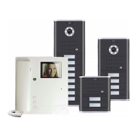
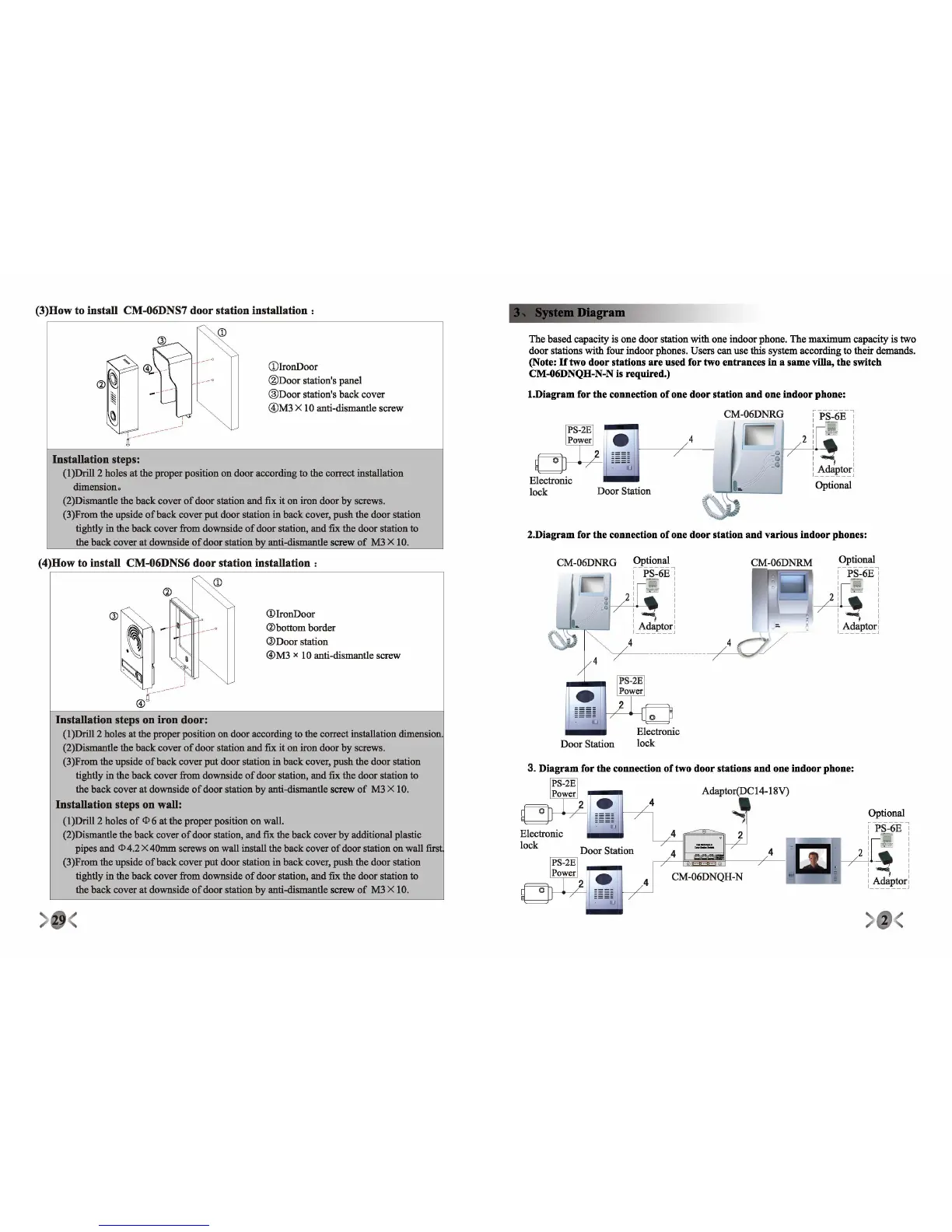
The
based
capacity is one
door
station
with
one indoor phone. The
maximum
capacity is
two
door
stations
with
four indoor phones. Users
can
use this system according to their demands.
(Note:
Iftwo
door stations
are
used for two entrances in a same villa, the switch
CM-06DNQH-N-N is requlred.)
2.Diagram for the connection of one door station
and
various indoorphones:
1.Diagram for the connection of one door station
and
one indoor phone:
:ps-6K:
I I
I I
I I
I I
I
I I
I I
i_~~I>to!j
Optional
CDlronDoor
®Door
station's panel
®Door
station's
back
cover
@M3X
10 anti-dismantle screw
Installation steps:
(1)Dri1l2 holes at the
proper
position on
door
according to the correct installation
dimension
0
(2)Dismantle the
back
cover
of
door
station
and
fix
it on iron
door
by screws.
(3)From the upside
ofback
cover
put
door
station in
back
cover,
push
the door station
tightly in the
back
cover
from downside
of
door
station,
and
fix the
door
station to
the
back
cover
at downside
of
door
station by anti-dismantle screw
of
M3 X 10.
(3)How to install CM-06DNS7 door station installation:
CD
Optional
--PS-6E :
.
~
-
:
I
I
I
I I
I I
i_~~I>to!j
, -
4
CM-06DNRM
Adaptor(DC14-18V)
Optional
'-PS::6EI
I
ll
, I
I I
I I
2 : :
I
I I
I I
: Adapter]
4'---_~~~_~
"
7
i
0/
4
r-="
I
Door
Station
CM-06DNRG
3. Diagram for the connection
oftwo
door stations
and
one indoor phone:
PS-2E
Power
2 , •
©
~
~
~
~
I
I
I
~
~
~
lJ
Electronic
lock
CD
Ironljoor
@bottom
border
®Door
station
®M3
x 10 anti-dismantle screw
Installation steps on iron door:
(1)Dri1l2 holes at the proper position on door according to the correct installation dimension.
(2)Dismantle the
back
cover
of
door
station
and
fix
it
on iron
door
by screws.
(3)From the upside
ofback
cover
put
door
station in
back
cover,
push
the door station
tightly in the
back
cover
from downside
of
door
station,
and
fix the
door
station to
the
back
cover
at downside
of
door
station by anti-dismantle screw
of
M3 X 10.
Installation steps on wall:
(1)Dri1l2 holes
of
ep6 at the
proper
position on wall.
(2)Dismantle the back cover
of
door station, and fix the back cover by additional plastic
pipes and
ep4.2 X
40mm
screws on wall install the
back
cover
of
door station on wall first
(3)From the upside
ofback
cover
put
door
station in
back
cover,
push
the door station
tightly in the
back
cover
from downside
of
door
station,
and
fix the
door
station to
the
back
cover
at downside
of
door
station by anti-dismantle screw
of
M3 X 10.
(4)How to instalI CM-06DNS6 door station installation:
CD
 Loading...