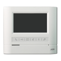
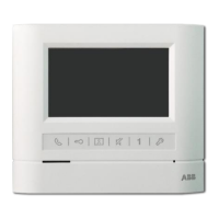
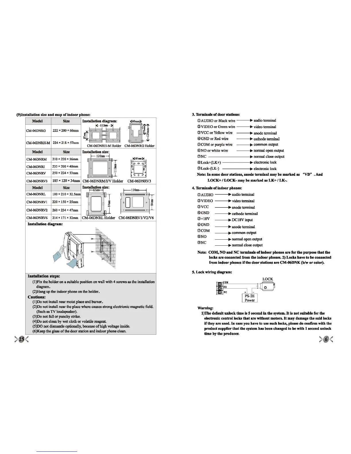
(9)Installation size
and
map
of
indoor
phone:
WCK
5.
Lock
wiring
diagram:
-----I.~
c
o
mm
on
output
---.~
n
ormal
open output
-----I.~
n
o
rmal
close output
Note:
COM,
NO
and
NC
terminals
of
indoor
phon
..
are
for
the
purpose
that
the
locks areconnectedfrom theindoorphones.2) Locks haveto be connected
from
indoor
phones
if
the
door
stations
are
CM-06DNK (b/w
or
color).
Warning:
l)The
defanlt
unlock
time
is 5 second in
the
system.lt
is
not
suitahle
for
the
eleetrouic
controllocks
that
are
withont
motors.
It
may
damage
the
said
loeks
if
they are used.
In
ease
yOD
have to use such locks, please du eeaflrmwith the
product supplier that the system
hai
been changed to be with 1 seeend unleek
time
hy
the
producer.
4. Terminals of indoorphones:
(j)AUDIO • •udio terminal
(J)VIDEO • video terminal
(l)VCC • anode terminal
OOGND
• cathode terminal
(l)+18V •
DCl8Vinput
®GND
• anode terminal
(DCOM
®NO
®NC
3. Terminals
of
door
stations:
(j)AUDIO or Black wire
• •udio terminal
(J)VIDEO or Green wire • video terminal
(l)VCC or Yellow wire • anode terminal
OOGND
or Red wire • cathode terminal
(l)COM or purple wire • common output
®NO
or white wire • normal open output
(DNC • uoruta1close output
®Lock+(LK+)
• electronic lock
®Lock-(LK-)
• electronic lock
Note: In somedoorstations,anodeterminalmaybe markedas "VD" .And
LOCK+
I
LOCK-
may
he
marked
as
LK+
I
LK-.
Model
Size
Installa~~~~m:
~
12mm
CM-06DNRG
222 x 200 x 66mm
~
~
~
o
--"-
~
M
0
0
~
0
o
CM-06DNRH-M
224 x 218 x
57mm.
CM-06DNRH-M
Holder
CM-{)6DNRG
Holder
Model
Size
In8tall~tion
~~
120mm
~.,~~
CM-{)6DNRM
210 x 220 x 56mm
:
D~
1
0
00
CM-{)6DNRI
235x200x40mm
0
D
~
CM-{)6DNRV
250 x 224x 53mm
.I
- -
o 0 0
CM-{)6DNRV3
185x 120 x 34mm
CM-06DNRMII/V Holder CM-06DNRV3
Model
Size
Ins~~.:~e:
f--
120
mm-------1
CM-{)6DNRL
100x 210 x
32.5mm
L
0=
u--r
I6 , "c
tr
Oe
,00
0
CM-{)6DNRVI
220 x 150 x 25mm
J
i
CM-{)6DNRV2
260 x 234 x 47mm
r
c
,
~
=
CM-{)6DNRV6
214 x 171x 32mm
CM-06DNRL Holder
CM-Q6DNRVIN2N6
Installation
diagram:
~
ff,"
-,--'-
l~
-
6
~
I
-',
I
-
~~
~
Installation
steps:
(I)Fix
the holder on a suitable position on wall with 4 screws as the Installation
diagram.
(2)Hang
up the indoor phone on the holder.
Cautions:
(1)00
not instalI near moist place and burner,
(2)00
not instalI near the place where causes s1rongelectrionic magoetic field.
(Such as TV loudspeakor).
(3)00
not fall or punchy strike.
(4)00
not clean by wet cloth or volatile reagent.
(5)DO not dismantle optionally, because
ofhigh
voltage inside.
(6)Keep the glass
ofthe
door station and indeor phone clean.
<>
 Loading...