Chapter 3 - Functional Description
DCS 500 12-Pulse Planning and Start-Up 3 - 1
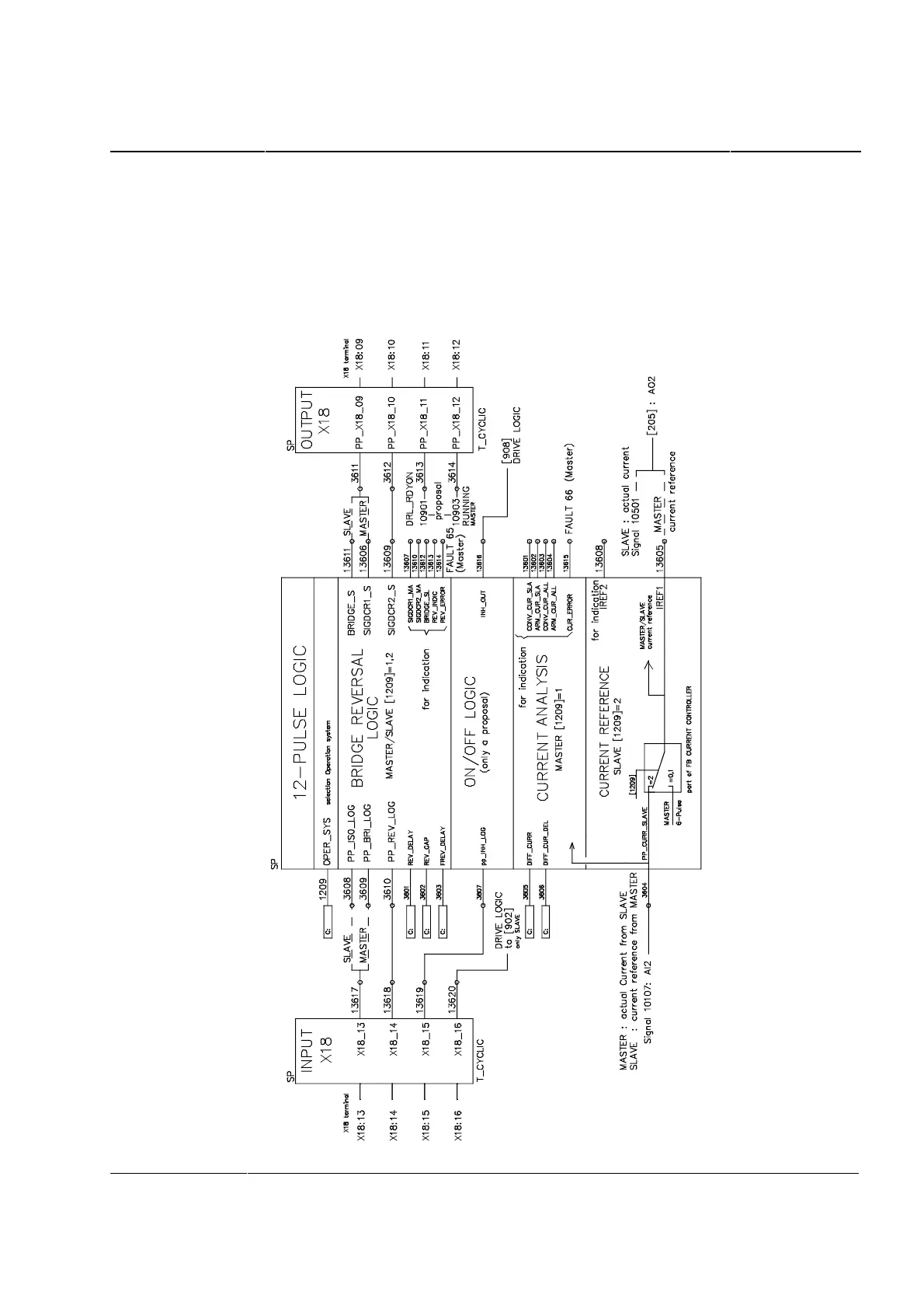
Block diagram
The signals and parameter settings depicted in the diagram are re-
quired for a speed-controlled 12-pulse drive with DCS 500 in a
Master-Slave configuration. The function block shown is included in
the basic software, and is activated when required using Parameter
1209.