10/24-4.10 EN Rev. 9 EasyLine EL3000 Series Data Sheet 17
Electrical connections
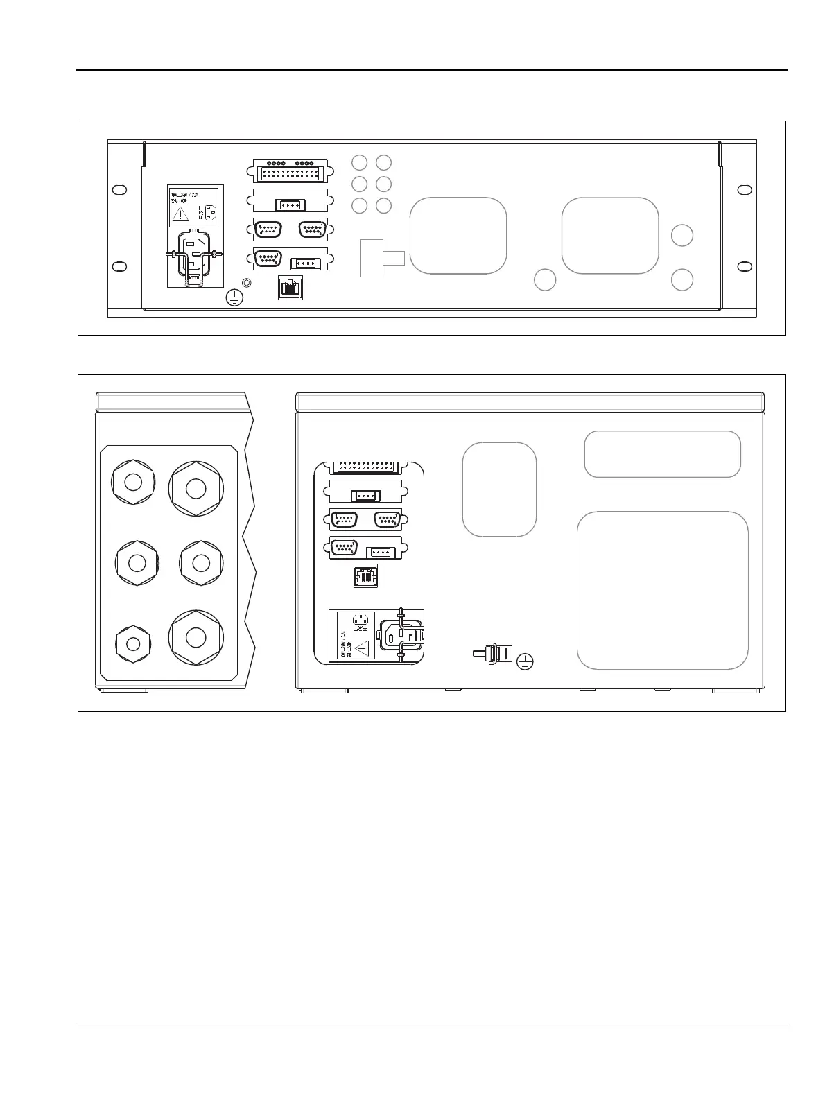
Power supply and signal lines model EL3020 (view from behind)
X01
7
2
3
4
5
61
10/100
BASE-T
-X27
-X25
-X23
-X21
-X20
-X22
-X24
-X26
Power supply and signal lines model EL3040 (view from below)
M25
M25
M20
M32
M25
M32
X01
7
2
3
4
5
6
1
10/100
BASE-T
-X27
-X25
-X23
-X21-X20
-X22
-X24
-X26
1 Power supply connection
(3-pin plug per EN 60320-1/C14; connection cable
supplied)
I/O modules (4 slots), options:
2 Digital I/O module (max. 3 modules)
3 Analog output module (max. 2 modules)
4 Modbus module (RS232 and RS485 interface)
5 Profibus module (RS485 and MBP interface)
6 Ethernet-10 /100BASE-T interface (8-pin RJ45 plug)
7 Potential compensation connection (max. 4 mm
2
)
Screwed cable glands for cable diameter:
M20 Power supply 5–13 mm
M25 Modbus/Profibus 8–17 mm
M25 Network 8–17 mm
M25 Analog outputs 8–17 mm
M32 Digital inputs/ outputs 12–21 mm
M32 Digital inputs/ outputs 12–21 mm
Notes
Both drawings show examples for the I/O modules equipment.
I/O module connection:
– The maximum capacity of terminals for stranded or solid
conductors is 1 mm
2
(17 AWG).
– The stranded conductor may be tinned on the tip or twisted
for simplified connection.
– When using wire end ferrules the total section should not
exceed 1 mm
2
, i.e. the maximum stranded conductor section
is 0.5 mm
2
. The Weidmüller PZ 6/5 crimping tool must be
used for crimping the ferrules.
Functional scope of the Ethernet interface:
– Communication with configuration software ECT for gas
analyzer configuration and software update.
– QAL3 data transfer if the QAL3 monitoring option is integrated
in the gas analyzer.

 Loading...


