11
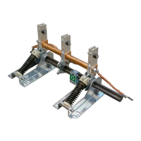
Rules for Installation of earthing switch EK6
When installing earthing switches in switchgear
panels, the following details must be taken into
account to achieve perfect switching functions:
• The active part of the earthing switch is sup-
plied in the open position and with preten-
sioned toggle springs.
• The earthing switch can be installed
in any position.
• Do not operate the switch without
earthing contacts!
• Install the active part and earthing contacts
without stress or distortion and parallel to each
other on a torsionally rigid and flat panel wall/
crossbeam and conductor bar respectively.
• Precisely maintain the spatial/dimensional posi-
tion of the earthing contacts relative to the ac-
tive part as shown in the dimensional drawing
for the relevant type of earth switch.
• Only use insulated mountings with a sufficient
cantilever strength. Tightening torque for
insulator has to specify producer of insulators.
• Fit the operating mechanism.
• The operating shaft can be moved after
the two setting rings have been released.
Observe the tightening torque of 4 Nm for
the M6 threaded pins.
Adjusting of the motion sequence
Adjust the motion sequence of the earthing
blades in relation to the earthing contacts
as follows:
1. Grease the contact areas.
2. Close the switch with the fixing bolts
in the earthing contacts loosely tightened.
3. Check that the blade pairs are properly
located on the contact tongues of the earthing
contacts and adjust if necessary.
4. Tighten the fixing bolts and carry out
a test switching operation.
5. Maximum permissible deviation between
the central position of the earthing blades and
the contact tongues of the earthing contacts:
-
EK6-3608-280, EK6-4008-280,
EK6-1212-210 and EK61212-275.
-
of earth switches in this manual.
- Measuring Point: Clearance between the
earthing blades and the contact tongues
during opening. Take care when handling
the switch!
6. Irrespective of the routine testing of the
relevant switchgear panels/switchboard
to IEC 62271-200, the earthing switch
is to be subjected to routine testing
in accordance with IEC 62271-102,
on completion of installation.
• Check for correct function of the high-speed
switching system when the switch has been
installed without stress or distortion.
• Check the tightening torque for the
M 12 hexagon nut on the short-circuiting
bridge, possibly removing a pair of earthing
blades to provide access. This torque is im-
portant for correct function! Rated tighten-
ing torque:
- Without lubricant: 86 Nm /with oil or
grease lubricated: 40 Nm.
- Bolt the copper earthing conductors to the
bearing brackets and connect the other
ends to the switchboard earthing bar.
- Perform at least 20 mechanical opening
and closing operations on the earthing
switch after completion of installation.
- Before energizing of the panel is recom-
mended to perform voltage drop test
on contacts.
Auxiliary switches for position indication
Auxiliary switches on the side wall of the
switchgear panel:
• Signaling of open and closed positions.
• Operation by rod mechanism (engages with
M 12 threaded bar).
—
Rules for installation
MAINTENANCE — RULES FOR INSTALLATION