Operation Manual / 4 Product description / A100-M axial
8 Disassembly and assembly / 8.10 Installing the compressor casing
© Copyright 2019 ABB. All rights reserved. HZTL4033_DE Revision C February 2019
8.10 Installing the compressor casing
Installing the compressor casing external part
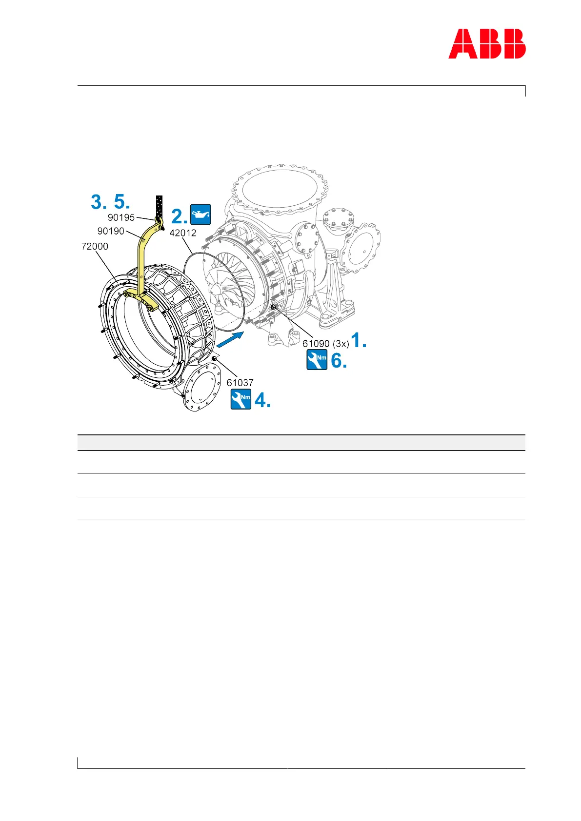
Fig.54: Installing the compressor casing
Part number A170-M A175-M
61037 M22
415 Nm
M24
490 Nm
61037 (nuts that are difficult to ac-
cess)
Pre-tightening torque 30 Nm
Tightening angle 45° ±5°
Pre-tightening torque 40 Nm
Tightening angle 45° ±5°
61090 M22
50 Nm
M24
50 Nm
Table40: Tightening torque (61037 / 61090)
1. Distributed evenly around the circumference, screw the press-off nuts (61090) onto the
studs of the bearing casing and turn them by hand until they are at the end of the thread.
2. Grease the new O-ring (42012) and fit it.
3. Fasten lifting device (90190 / 90195) to compressor casing (72000) and secure to crane.
4. Position the compressor casing(72000).
Tighten nuts (61037) crosswise.
5. Remove lifting device (90190 / 90195).
6. Tighten the three press-off nuts (61090) against compressor casing (72000) by applying
the corresponding tightening torque.
Page 81 / 108