1 Procedures
1.2. Procedure for MultiMove systems
93HAC 027097-001 Revision: B
© Copyright 2006 ABB. All rights reserved.
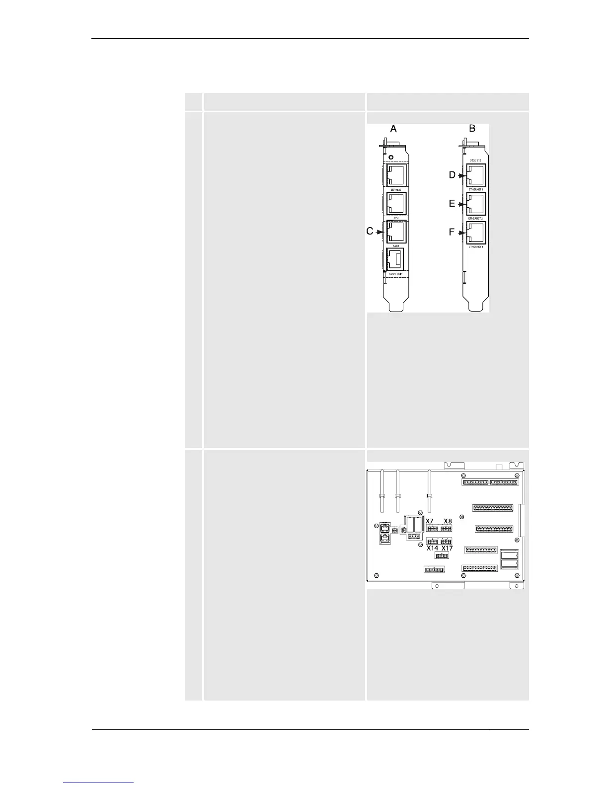
2. Connect the Ethernet cables from each
Drive Module to the Control Module
Ethernet card.
Make sure the Drive Modules are
connected in the correct order! The order
must correspond to the order in which the
key strings are entered when creating the
system.
xx0400001141
Connections:
• A: Robot communication card
• B: Ethernet card
• C: Ethernet connection to Drive
Module #1 (connected on delivery)
• D: Ethernet connection to Drive
Module #2
• E: Ethernet connection to Drive
Module #3
• F: Ethernet connection to Drive
Module #4
3. Before connecting the safety signal cables,
remove jumpers from connectors X7, X8,
X14 and X17 as required by the number of
Drive Modules to connect.
Connect the safety signal cables from each
Drive Module to the Control Module panel
board as shown in the figure.
xx0400001295
Connections:
• X7: safety signal cable to Drive
Module #1(connected on delivery)
• X8: safety signal cable to Drive
Module #2
• X14: safety signal cable to Drive
Module #3
• X17: safety signal cable to Drive
Module #4
Action Info
Continued
Continues on next page