4 LST200 | ULTRASONIC LEVEL TRANSMITTER | CI/LST200-EN REV. C 5
LST200 | ULTRASONIC LEVEL TRANSMITTER | CI/LST200-EN REV. C
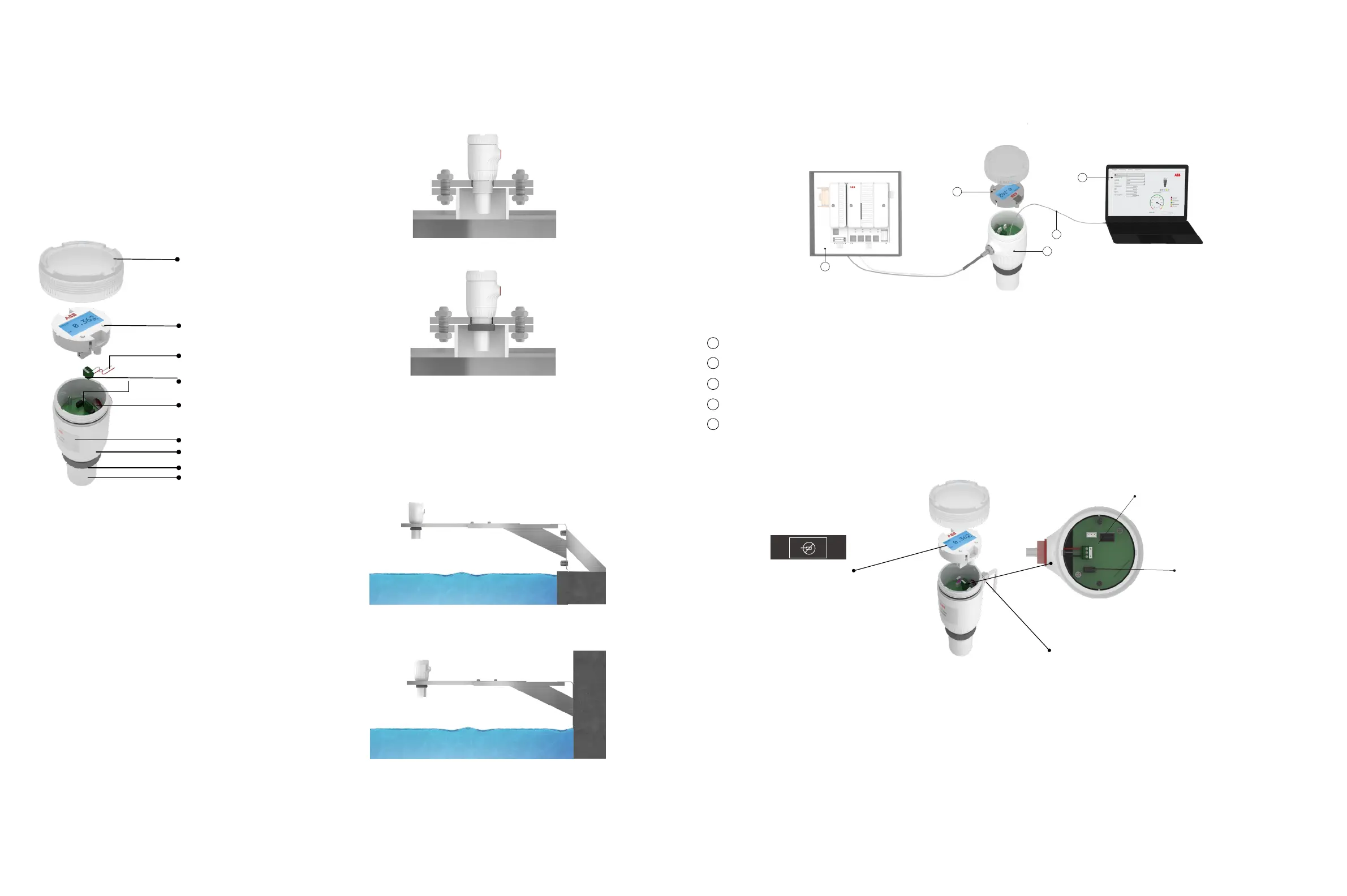
Cyber security label
Cable glan
d
Interface cable and LCD port
Power supply terminal
7 To connect the LST200 instrument
Housing cover
LCD (only for LCD version )
Cable connector and electronics
Connection ports
(For M20 x 1.5 cable gland)
Nameplate
Enclosure
Sensor
Mounting nut
Test wire (for test only,remove before
installation)
Floor mounting
Wall mounting
5 Mounting with bracket
For open channel or basin, mounting bracket may be needed,
contact ABB if you need the brackets or further suggestion.
6 Typical LST200 connection
LST200 can be setup either through the LCD or on a computer and it’s a 2-wire loop powered device that can be connected directly
with DCS or PLC
4 Installation
The LST200 transmitter can be mounted directly on a tank/
flange using either a nut or a sleeve.
1.Remove the temporary plastic cap from the electrical connection port
2.Remove the housing cover and the LCD (for LCD option)
3.Remove the green terminal with + - mark
4.Route the connection cable through the cable gland and the electrical connection port
5.Connect the positive lead to the + terminal, and the negative lead to the – terminals. Connect the shielding layer to GND if
possible
6.Put back the green terminal
7.For LCD version, put back the LCD and paste the cyber security label to cover one of the LCD screws
8.Put back the housing cover. Turn it so as to seat the O-ring into the housing, then continue tightening by hand until the cover
contacts the housing
9.Power up the instrument by switching on the circuit breaker
3 What’s in the box
Check for damages to the included parts:
• LST200 (see below picture)
• Quick Start Guide
• Cyber security label (only for LCD option)
• Certificate of calibration and inspection
Should any part of the package be damaged upon reception,
contact ABB customer service as indicated on the back cover of
your user guide.
Figure 1: Main components of LST200
Figure 2: Direct mounting variations
Figure 3: Mounting with bracket
Figure 5: Cable connection
Figure 4: Typical connection
Using the nut (recommended hole size 60mm)
Using the thread
DCS or PLCA
B
C
E
D
Computer with configuration software (through ABB FIM tool with FDI package)
LST200
Interface cable (specially designed for LST200)
LCD
C
D
A
E
B
4~20mA
ABB FIM Tool
FDI Package