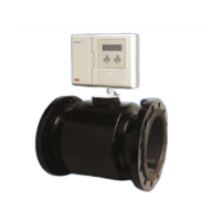
MagMaster
Electromagnetic flowmeter 1 Electrical Installation
2 IM/MM2WM–EN Rev. A
1 Electrical Installation
Install the WaterMaster transmitter in accordance with User Guide, OI/FET100–EN.
1.1 Configuration DIP Switches
Remove the transmitter cartridge as detailed in the User Guides, OI/FET100–EN.
The transmitter backplane PCB contains 3 DIP switches as shown in Fig. 1.1.
For retrofit applications the flowmeter sensor memory, that contains all the sensor-related calibration factors
and settings, is not present on the older MagMaster style of flowmeter sensors. For these flowmeters this
'sensor memory' is switched to use the fitted memory on the backplane PCB of the WaterMaster. This
must be turned on using SW3.
SW3 – Defines the 'Sensor Memory' EEPROM location
OFF= Remote sensor memory
ON = Use Integral transmitter sensor memory
For WaterMaster electronics working with MagMaster sensors (also called 'Retrofit' units) set the DIP
switches as shown in Fig. 1.2. Leave SW1 & SW2 unaltered as they are not part of the retrofit upgrade
detailed here.
Note. These upgrade instructions and the use of WaterMaster with existing MagMaster sensors is
supported only on the MF/F product code style of sensors, not the MF/E type.
Fig. 1.1 Configuration DIP Switches
Fig. 1.2 Configuration DIP Switches
Note. The backplane-fitted 'sensor memory' enables the transmitter cartridge to be changed in a repair
situation (all the settings are retained on the backplane when a new transmitter cartridge is fitted). If the
transmitter enclosure is replaced for any reason, re-install the new transmitter (refer to OI/FET100–EN)
and perform all of the retrofit procedures detailed in this publication (IM/MM2WM–EN).
Configuration
DIP Switches
SW3 SW2 SW1
OFF
ON
SW1 – Read-only / MID Lock
SW2 – (Future Product)
SW3 – Internal Sensor Memory
DIP Switch Functions
Configuration
DIP Switches
SW3 SW2 SW1
OFF
ON
SP033 Adam Street Wynnum SPS - WaterMaster - Electromagnetic Flowmeter -
OIML R49 Class 1 450mm - User Guide
 Loading...
