M
M
NS iS
NS iS
S
S
y
y
s
s
t
t
e
e
m
m
S
S
e
e
t
t
u
u
p
p
2
2
ABB MNS iS System Setup & Operation Quick Guide / System Release 6.0 – Rev.2 / Aug. 2011
2
2
3
3
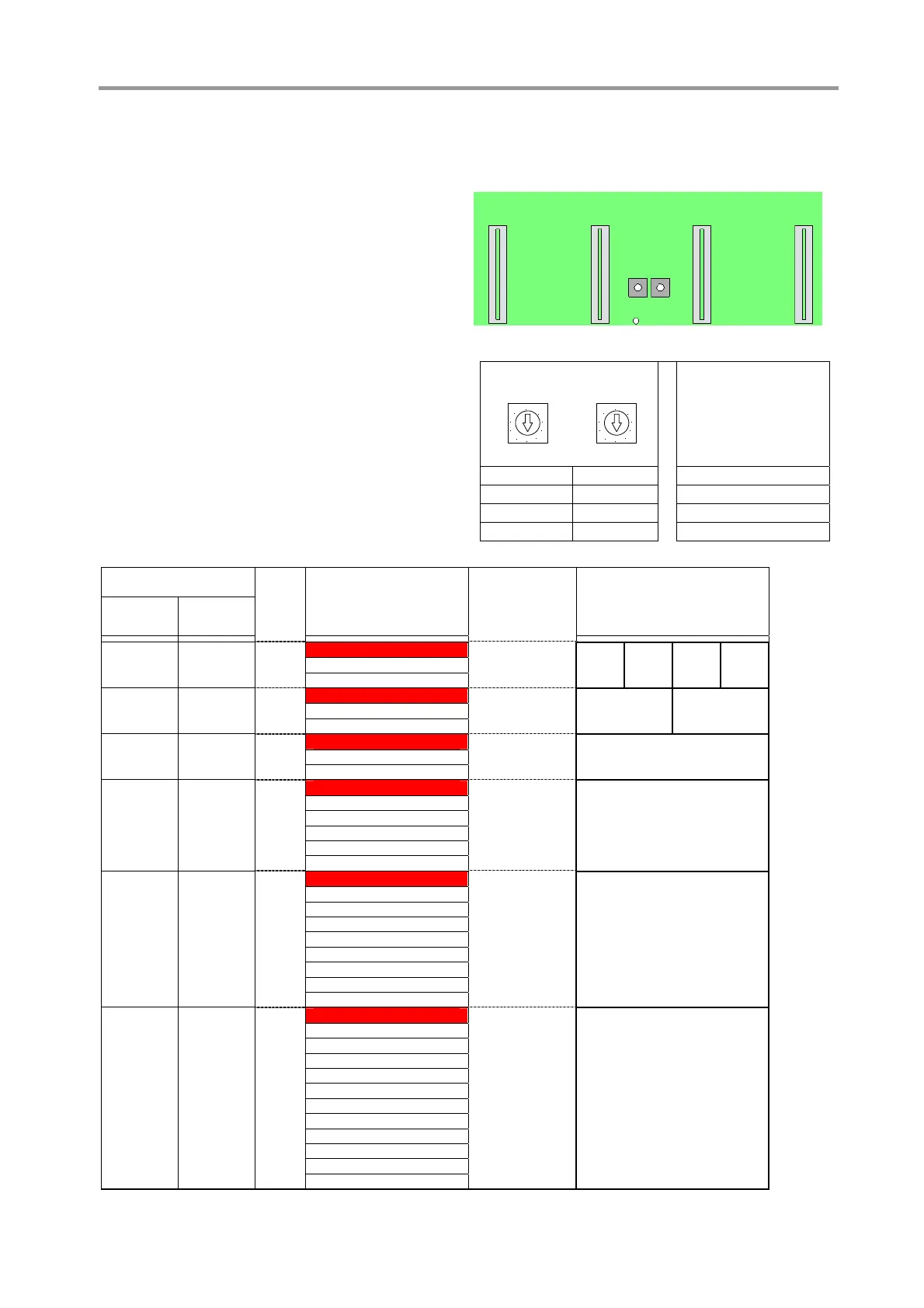
BCD rotary switches
x10 x1
4 3
2
1
Figure 23 BCD rotary switches on control condapter
2.2 Module location setting
Each single MControl as well as MStart / MFeed
module position is defined in the MNS iS project
configuration data.
As a precondition for the allocation between
particular MControl and MStart / MFeed devices
the vertical position of the MControl in the switch-
board has to be set.
The BCD rotary switches used for this setting are
located on the backplane of the control condap-
ter, see Figure 19. Both switches indicate the
horizontal position of the module top edge as
decimal code.
The horizontal positions 1 through 4 on each
level are registered automatically with the
insertion of the particular MControl.
Sample configuration
BCD rotary switch
x 10 x 1
0
7
8
9
5
4
6
2
3
1
0
7
8
9
5
4
6
2
3
1
Position Position
Module location
(2E steps)
0 1…9 01…09
1 0…9 10…19
2 0…9 20…29
3 0…6 30…36
BCD rotary switch
position
x 10 x 1
Horizontal level of
module in switchboard
(upper edge)
Module height
(Sample
configuration)
Vertical position of
module in compartment
(No. of MControl main board)
1
2 4 x 6E/4 1 / 1 1 / 2 1 / 3 1 / 4
0 1
3
4
5 2 x 6E/2 4 / 1 4 / 3
0 4
6
7
8 6E 7 / 1
0 7
9
10
11
12 12E 10 / 1
13
14
1 0
15
16
17
18
19 16E 16 / 1
20
21
22
23
1 6
24
25
26
27
28
29
30 24E 25 / 1
31
32
33
34
35
2 5
36