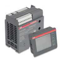
Do you have a question about the ABB LVS Digital FC610 and is the answer not in the manual?
| Brand | ABB |
|---|---|
| Model | LVS Digital FC610 |
| Category | Control Systems |
| Language | English |
Information about ABB trademarks and copyrights.
Identifies the intended audience for the manual.
Explains the meaning of various icons used in the document for safety and information.
Describes the intended uses and applications of the FC610 device.
Describes the function and purpose of each terminal block on the FC610 basic unit.
Details specific wiring configurations for digital inputs, outputs, and communication.
Lists the electrical parameters measured by the FC610 and their accuracy.
Details the measurement of active, reactive, and apparent energy.
Explains how demand values are calculated and presented.
Describes the measurement of total and individual harmonic distortions.
Details the monitoring and calculation of current unbalance.
Details the monitoring and calculation of voltage unbalance.
Explains the settings and operation for voltage dip detection.
Explains the settings and operation for voltage swell detection.
Details the settings and operation for voltage interruption detection.
Describes the over current monitoring and alarming function.
Explains monitoring of voltage/current phase sequence for wiring error prevention.
Details monitoring of device status, operation counters, and running/stopped times.
Details the functions of the buttons on the HMI panels.
Explains the meaning of various icons displayed on the HMI.
Outlines the structure of the main display pages on the HMI.
Describes how to navigate between different parameter groups on the HMI.
Explains how to navigate through individual pages within a display group.
Lists and describes the alarm messages generated by the FC610.
Details settings for communication parameters, display panel, and real-time clock.
Specifies fundamental feeder information like control and ratings.
Configures power quality and load supervision functions.
Allows setting the time interval for demand value calculation.
Configures parameters related to device maintenance and event recording.
Allows viewing firmware versions of the FC610 and connected modules.
Outlines the methods for configuring FC610 parameters.
Lists the preloaded factory settings for easy startup.
Describes the memory area for re-mapping parameter addresses.
Lists electrical and mechanical specifications of the FC610 unit.
Details the performance characteristics of various functions according to standards.
Describes characteristics related to power quality evaluation functions.