5
5
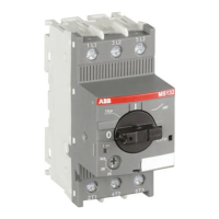
Manual motor
protectors
5.2 Low Voltage Products & Systems
AC 1000 - 11/03 ABB Inc. • 888-385-1221 • www.abb-control.com
1M
246
135
I> I>I>
L1 L2 L3
1C
T1 T2 T3
INCOMING LINES
ISOMAX MCCB
or
Fusible Switch
(If specified)
A
B C
2M
L1 L2 L3
2C
T1 T2 T3
3M
246
135
I> I>I>
L1 L2 L3
3C
T1 T2 T3
4M
246
135
I> I>I>
L1 L2 L3
4C
T1 T2 T3
5M
246
135
I> I>I>
L1 L2 L3
5C
T1 T2 T3
MOTOR MOTOR MOTOR MOTOR MOTOR
246
135
I> I>I>
Selection
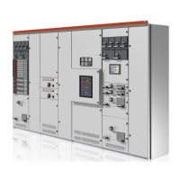
Group installation is an approach to building multi-motor control systems in
accordance with Section 430-53 of the National Electrical Code. The selection
of components used in group installations is a simple process which consists of
several steps.
• First is the selection of the appropriate fuse as Branch Circuit Protective Device
(BCPD).
• Second is the selection of the appropriate motor starter and protector.
• Third, the selected MMP must be checked for UL listing with the selected
BCPD and the available short circuit current at the application location.
1. Fused disconnect
Calculate maximum fuse size according to NEC 430-53 (c). I
max
(fuse size) =
175% x FLC (full load current for largest motor) + the sum of FLC (full load current
for largest motor) + the sum of FLC values for other motors on that branch using
NEC Table 430-150 on the right. Select fuse from NEC Table 240-6 below. Where
I
max
falls between two fuse ampere ratings NEC 430-53 (c) permits going to the
next high ampere rating.
2. Motor protector selection
Select the proper MMP catalog number for each motor load from the following
pages based on the actual motor full load current (FLA) using the “Thermal setting
range” column for reference.
3. MMP Interruption ratings
Using the interruption ratings table on the next page, identify the system
application voltage and interrupting capacity for the type of fuse selected in step
1 above.
NEC 240-6 Standard fuse amperes
15, 20, 25, 30, 40, 45, 50, 60, 70, 80, 90, 110, 125, 150, 175, 200, 225, 250, 300,
350, 400, 450, 500, 600, 700, 800, 1000, 1200, 1600
Examples: Select components for protecting the following 3-phase, 460VAC,
squirrel cage induction motors. The nameplate data are:
1/2 HP, 1.0 FLA; 3 HP, 4.8 FLA; 5 HP, 7.6 FLA; 7.5 HP, 11 FLA;
10 HP, 14 FLA.
Example: using fused disconnect
• I
max
= 175% x 14 + (11 + 7.6 + 4.8 + 1) = 48.9A
• Fuse rating using Table NEC 240-6 = 50A
• Minimum disconnect size = 115% x Total FLA
• NEC 430-150 table = 115% x (14+ 11 + 7.6 + 4.8 + 1) = 44.16
Disconnect for 50A fuses is ok.
General information
1 These values of full-load current are for motors running at speeds usual for belted motors and motors with normal torque characteristics. Motors built for especially low speeds or high torques may
require more running current, and multispeed motors will have full-load current varying with speed, in which case the nameplate current rating shall be used.
The voltage listed are rated motor voltages. The currents listed shall be permitted for system voltage ranges of 110 to 120, 220 to 240, 440 to 480, and 550 to 600 volts.
Induction type
squirrel cage & wound rotor
1
Horsepower
230V 460V 575V
amps amps amps
1/2 2 1 .8
3/4 2.8 1.4 1.1
1 3.6 1.8 1.4
1.5 5.2 2.6 2.1
2 6.8 3.4 2.7
3 9.6 4.8 3.9
5 15.2 7.6 6.1
7.5 22 11 9
10 28 14 11
15 42 21 17
20 54 27 22
25 68 34 27
NEC Table 430-150 full load current, 3ph AC motor
Note: Refer to NEC 310-1 and NEC 430-53(d) for cable sizing.
For full load currents of 208 and 200 volt motors, increase the
corresponding 230 volt motor full-load current by 10% and 15%,
respectively.
MS325 data
1/2 1.0 MS325-1.0 A9C
3 4.8 MS325-6.3 A9C
5 7.6 MS325-9.0 A9C
7.5 11 MS325-12.5 A12C
10 14 MS325-16 A16C
Motor rating at 460V
MS325 Contactor
Horsepower FLA, AC3

 Loading...