Do you have a question about the ABB M10 Series and is the answer not in the manual?
Information for understanding, engineering, testing, system integration, or commissioning of the M10x product.
Explains the meaning of warning, caution, information, and tip symbols used in the publication.
Lists and defines terms, acronyms, abbreviations, and definitions used in the document.
Lists related ABB documentation and system versions applicable to M10x products.
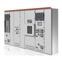
Describes the M10x as an intelligent motor control and protection device for ABB low voltage switchgear.
Lists available M10x product variants, including M101, M102, and communication types.
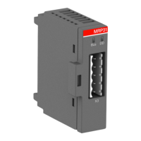
Details the main unit construction with integrated CT and the operator panel (MD21/MD31).
Describes the AO11 module, an optional add-on for providing analogue output.
Specifies M10x enclosure material and details the M10x-TCP Ethernet module EM01.
Provides dimensions and mounting information for M10x, MD21, and MD31 units.
Describes terminal blocks and connectors for digital inputs, outputs, communication, and power.
Details digital inputs and PTC inputs on terminal block X1 for different M10x types.
Explains the connection of the MDx operator panel to the M10x via the X2 interface.
Details Modbus RTU, Profibus DP, and Modbus TCP communication interfaces available through X3.
Describes digital output relays, contactor control relays, power supply, and ground terminals.
Shows an example of the terminal layout for the M102-M 24VDC product type.
Provides typical wiring diagrams for the M102-M 24VDC Direct On-Line starter.
Lists various starter types supported by M10x for different control applications.
Explains the use of contactor and current feedback for motor status verification.
Describes the NR-DOL starter as a basic type for one-direction motor driving.
Describes the REV-DOL starter controlling CW and CCW directions via outputs A and B.
Describes the actuator starter for controlling valves and actuators using limit switches.
Describes the NR-S/D starter for star-delta connection, reducing starting current and torque.
Describes the NR-2N starter for controlling motor speed with separate windings.
Describes the autotransformer starter for minimizing voltage drop during startup.
Describes the NR-softstarter for controlling motor accessories and adjusting motor voltage.
Describes the REV-softstarter, similar to NR-softstarter but supporting reversing.
Describes the Contactor feeder for symmetric/single-phase loads, offering measurement and control.
Describes the Contactor feeder/RCU starter type, controlled by RCU for direct contactor control.
Describes the Feeder control logic for circuit breaker loads, providing measurement and control.
Lists protection and supervisory functions available in M10x for M101 and M102.
Explains thermal overload protection (TOL) that protects the motor against overheating.
Explains the purpose of the TOL bypass function and its activation conditions.
Explains stall protection used to protect the motor from jams and excessive overload.
Explains long start protection against locked or stalled rotors during startup.
Explains phase failure protection against phase current loss using ILmin/ILmax ratio.
Explains unbalance protection against motor unbalance conditions using ILmin/ILmax ratio.
Explains underload protection against low motor load conditions using ILmax/In ratio.
Explains noload protection against no load conditions, similar to underload protection.
Explains earth fault protection using a residual current transformer, with default suppression.
Explains PTC protection against high temperatures using PTC sensors.
Explains start limitation to protect motors and processes from excess starts in an interval.
Explains phase sequence protection against incorrect motor connection.
Explains undervoltage protection against voltage dips using ULmin criterion.
Explains autorestart function for M102 to restart motors after voltage dips via different modes.
Explains failsafe functionality supervising communication and defining actions upon failure.
Describes main switch supervision for safe operation and response to position changes.
Defines control authority and lists access groups: Local hardwiring, Remote fieldbus, MDx control.
Explains assigning control access using selector switch functions (local or soft).
Explains M10x support for hardwired local selector switch via DI inputs.
Explains MD control access, assignable via configuration or DI, independent of local/remote mode.
Lists available configurable digital inputs for 24VDC and 110/240VAC types.
Explains Start1/Start2 for start control and Stop for stop control via local hardwiring.
Describes Process interlock1 and interlock2 for time-dependent trip/alarm/stop features.
Explains Emergency stop input and PLC control inputs for jogging control.
Explains Loc/R input and Main Switch Supervision input for control access and protection.
Describes general alarm and trip functions, and specific alarm/trip functions for outputs.
Lists parameters monitored by M10x for M101/M102: Power, Motor status, Diagnosis, Maintenance.
Explains M10x monitoring of motor/starter service condition for maintenance scheduling.
Describes M10x counting starts and running hours, issuing alarms when levels are exceeded.
Introduces MD21 and MD31 operator panels as accessories for M10x local operation.
Details the four sets of configurable LEDs on the MDx panel and their functions.
Compares control buttons on MD21 (7 buttons) and MD31 (3 buttons).
Shows the MD21 display window with its elements, indicators, and navigation.
Explains MD21 display pages and how alarm messages appear on the display window.
Explains navigation through the M10x configuration menu using buttons and menu trees.
Explains password protection on MD21 panel to prevent unauthorized operations.
Shows the menu tree structure for parameter configuration within the operator panel.
Lists the three communication protocols: MODBUS RTU, PROFIBUS DP, and MODBUS TCP.
Describes the MODBUS RTU interface, its RS485 standard, and master/slave configuration.
Describes the PROFIBUS DPV1 interface, its multi-master/slave nature, and RS485 physical interface.
Describes MODBUS TCP connection via Ethernet and EM01 interface, supporting various topologies.
Explains parameter configuration via MD21, MCUSetup software, or fieldbus.
Describes setting parameters via MCUSetup software connected to MD21/MD31.
Explains parameterization via Modbus RTU or Profibus DP protocols.
Explains the self-diagnosis program for checking hardware and software, including Watchdog.
Explains selecting the TEST option for comprehensive health checking of M10x and MD21.
Lists fault conditions, descriptions, possible causes, and suggested actions.
Provides detailed actions for troubleshooting various fault conditions like Phase unbalance, Underload, etc.
Provides technical specifications for main circuit, control circuit, power supply, and response timing.
Details fieldbus protocols, operating conditions, humidity, and derating information.
Specifies metering accuracy and covers mounting, dimensions, wiring size, and tightening torque.
Lists relevant standards for low voltage switchgears and EMC compliance.
| Brand | ABB |
|---|---|
| Model | M10 Series |
| Category | Controller |
| Language | English |