4 Sub-Assemblies
PCS100 ESS User Manual | 2UCD190000E001 rev. J 19
4.3 PCS100 Master Module
Each PCS100 ESS system has one Master Module that controls the over-
all system operation from a central point by coordinating the function of all
PCS100 modules.
The Master Module controls the operating state of the overall system and
combines the measurements and feedback from all the PCS100 modules
into a single data set. It also identifies significant events in the system
(e.g. a fault state of a module) and stores them in an event log. Further-
more, it performs the system-wide input voltage sensing and calculates
the reference values for the PCS100 modules based on the system-wide
reference values set by the operator.
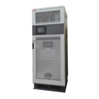
In case of cabinet systems, the Master Module is called the Auxiliary Mas-
ter Module and includes an internal 26.5 Vdc power supply and a 600ms
hold-up circuit in case of AC supply failure. The master module is fed via a
230V 50/60Hz Supply. In addition, the power for the fan supply (230Vac)
also is provided from an external source.
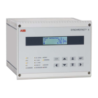
In case of rack systems, the Master Module is referred to as PCS100
Compact Master Module and does not contain an internal power supply.
Figure 4-4 shows a Compact Master Module.
Figure 4-4: PCS100 Compact
Master Module
Connections on the Master Module
The PCS100 ESS includes several control and control power connections for local and remote control and moni-
toring of the system. All terminals are located on the PCS100 Master Module and are suitable for wires up to 2.5
mm
2
cross section.
The following sections describe these connections in more detail. It includes some information on cabinet sys-
tems, however, the main focus is on rack systems as they still have to be assembled during installation.
4.3.1.1 Digital I/Os and Power Terminals
On the PCS100 Compact Master Module (rack systems) shown in Figure 4-5 there are digital input and output
terminals to activate remote control and monitor the status of the system, as well as power terminals to supply the
compact master from an external 26.5Vdc source.
1
The numbering of these terminals is shown in Figure 4-6 to-
gether with a short description in Table 4-1. In comparison the Auxiliary Master Module used in cabinet systems is
shown in Figure 4-7.
Figure 4-5: PCS100 Compact Master Module
Note:
1
In case of cabinet systems the master module is fed from an internal 26.5Vdc power supply.