For full instructions please follow the product manual which can be found on our web For full instructions please follow the product manual which can be found on our web
Hazardous voltage. Will cause death or serious injury. Turn off and lock out all power
supplying this device before starting work on this equipment.
To prevent an unintended direct start it's important to first power on the control supply
voltage. This will energize the bypass relays before mains are powered on to ensure the
relays are in open state.
Connecting Softstarters PSE18...PSE370 Inside
Delta will cause damage to the equipment, and
there is a risk of death or serious injury.
Ensure a free flow of air through the product.
Risk of damage to property. Ensure that no liquids, dust or conductive parts
enter the softstarter.
Using a too small enclosure and/or failure to follow the instructions in other
ways, may result in overheating of the PSE Softstarter and operational
disturbances.
—
Quick start guide
PSE18...370
Mechanical installation
—
Quick start guide
PSE18...370
Electrical installation
Page 3/4Page 2/4
30
O
30
O
O
PSE 18-600-70
PSE 18-600-70
PSE 18-600-70
PSE 18-600-70
C
A
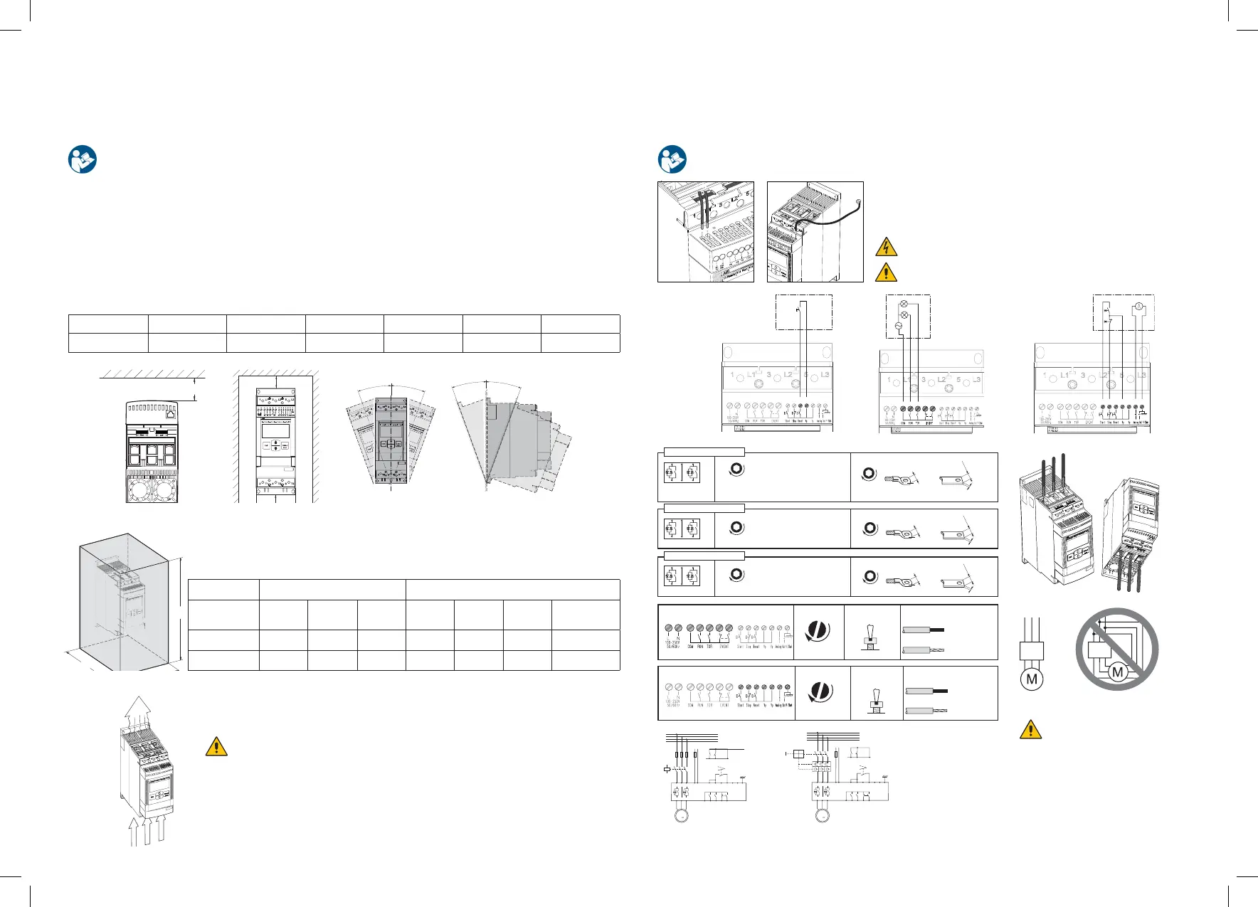
Mounting
The PSE Softstarters exist in three different physical sizes which are designed to be mounted with M6 bolts,
or bolts of equivalent dimension and strength. Verify the drilling plan on top of the box.
A (mm) B (mm) C (mm) A (in) B (in) C (in)
PSE18...370 20 10 100 0.787 0.394 3.937
8
4
5
6
7
9
10
11
12
13
14
PSE 18-600-70
81 2 3 4 5 6 7 9 10 11 12 13 14
Reset
PSE 18-600-70
81 2 3 4 65 7 9 10 11 12 13 14
AC
PSE 18-600-70
81 2 3 4 5 6 7 9 10 11 12 13 14
Start
Stop
Electrical installation
1. Connect the control supply voltage on terminals 1 and 2.
2. Connect the start/stop circuit and other I/Os.
3. Connect the mains on L1/L2/L3 and the motor to T1/T2/T3.
M8
1L1
2T1 4T2 6T3
3L2 5L3
max
22 mm
(0.866 in)
max
20 mm
(0.787 in)
max
5 mm
(0.197 in)
11/6-16 UNF-2A
275 lb.in
PSE142...170
1L1
2T1 4T2 6T3
3L2 5L3
3/4-16 UNF-2A
375 lb.in
PSE210...370
1L1
2T1 4T2 6T3
3L2 5L3
2,5 .. 10 mm
2
ATK185: AWG4 to 300kcmil
Al Cu 75°C only
2x2,5 .. 2x10 mm
2
AWG12 .. 6
6 Nm - 53 lb.in
8 Nm - 71 lb.in
10 .. 70 mm
2
2x10 .. 2x70 mm
2
AWG6 .. 2/0
M6
9 Nm - 80 lb.in
Using connection module
Using connection bars
max
30 mm
(1.181 in)
max
30 mm
(1.181 in)
max
10 mm
(0.394 in)
M10
28 Nm - 240 lb.in
Using connection bars
max
24 mm
(0.945 in)
max
22 mm
(0.866 in)
max
8 mm
(0.315 in)
M8
18 Nm - 160 lb.in
Using connection bars
Using connection module
Cu 75°C only
ATK300: AWG4 to 400kcmil
ATK300/2: AWG4 to 500kcmil or
2xAWG4 to 2x500kcmil
Al Cu 75°C only
Using connection module
Cu 75°C only
1 2 3 4 5 6 7
8 9 10 11
12 13 14
0,2 .. 4 mm
2
2x0,2 .. 1,5 mm
2
0,2 .. 4 mm
2
2x0,2 .. 1,5 mm
2
AWG 10 ... 24
0,5 Nm - 4,3 lb.in
4 x 0,8 mm
(0.157 x 0.031 in)
M3
1 2 3 4 5 6 7
8 9 10 11
12 13
0,2 .. 2,5 mm
2
2x0,2 .. 1,5 mm
2
0,2 .. 2,5 mm
2
2x0,2 .. 1,5 mm
2
AWG 12 ... 24
0,5 Nm - 4,3 lb.in
3,5 x 0,6 mm
(0.138 x 0.024 in)
M3
14
PSE
L1
L2
L3
N
KM1
1L1 3L2 5L3
2T1 4T2 6T3
6 7
NC NO
543
Run
TOR Fault
U
V
W
1 2 148 9
11
8 9
11
1210 13
M
3
Start Stop
Stop
Start
L N
L2
L3
N
MCCB
1L1 3L2 5L3
2T1 4T2 6T3
6 7
NC NO
543
Run
TOR Fault
U
V
W
1 2 148 9
11
8 9
11
1210 13
M
3
Start Stop
Stop
Start
L N
PSE
Circuit diagram PSE18-370
(Fuse and contactor version)
Circuit diagram PSE18-370
(MCCB version)
Inside Delta
IEC UL
H (mm) W (mm) D (mm) H (in) W (in) D (in) min number
of latches
PSE18...105 610 508 305 24 20 12 2
PSE142...370 762 610 305 30 24 12 4
Check that the distance to wall and front, as well as the mounting angle fulfills the requirements.
Mechanical installation
1. Follow the drilling instructions which can be found on the top part of the shipping box.
2. Make sure to have enough space according to our table below.
3. Install the product safely in place (may need two persons).
4. Make sure to mount the product in correct orientation according to the picture below.
In Line
In applications where the softstarter is installed in an enclosure, make sure that the
enclosure size is not smaller than the minimum recommended. Select size from the
applicable table for IEC or UL.
 Loading...