1MRS750527-MUM
)HHGHU7HUPLQDO
Technical Reference Manual, General
5()B
25
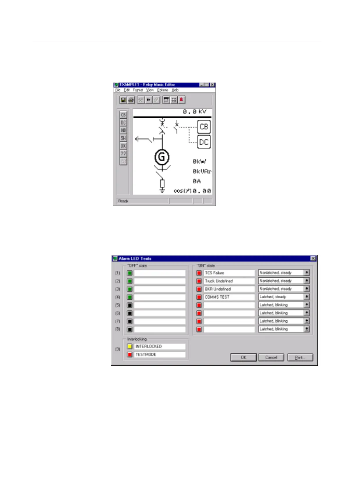
The MIMIC picture may include a single-line diagram, measured values with units,
free texts, etc. The object status indicators (open, closed, undefined) are drawn
according to the customer’s requirements. Note that the operation of the objects
themselves is determined by means of the Relay Configuration Tool.
)LJ 0,0,&FRQILJXUDWLRQZLWKWKH5HOD\0LPLF(GLWRU
The contents of the alarm view are configured with the Relay Mimic Editor by
defining the ON and OFF state texts (max 16 characters), see Figure 4.1.2.2.-2
below. For defining the corresponding LED colors refer to section “Alarm LED
indicators” on page 71.
)LJ $ODUPFKDQQHOFRQILJXUDWLRQ
Interlocking LED texts can also be defined in the view illustrated above, but the
interlocking LED colors cannot be changed. For the operation of the interlocking
LED, refer to section “Interlocking” on page 73.
REF_MI

 Loading...


