Quick Start Guide For The DNP Orion To ABB REL 356 Relays Using Modbus
4
3. Configure the IED port in RS 485 mode. The IED port is shown in Figure 1 or 1a depending upon the
unit, illustrations 3 and 3a. Some rack mount units and all Table Top ORION units have a DB 9 port
for RS 485 device connection whereas some Rack Mount ORION units may have three screw
terminals for an IED port physical connection. FOR AN ORION RACK MOUNT UNIT: Remove the
two screws from the rear of the unit as shown in Figure 1, illustration 4. Slide the metal cover away
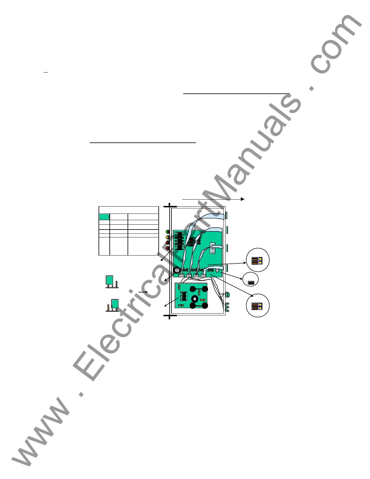
from the unit to expose the electronic boards contained within the enclosure. As shown in Figure 3,
five jumpers , JP 11, JP 12, JP 13, JP 14, and JP15 shall be placed in the appropriate positions for
RS 485 communication as indicated in Figure 3 (JP 11 through 14 in the closed position and JP 15
closed to insert resistor termination). Breakouts of each of the jumper locations are shown in
Illustration 1 and Illustration 2. The position of the jumpers in the “open” or “closed” positions are
highlighted. FOR AN ORION TABLE TOP UNIT: For the Table Top Unit the instructions for dis-
assembly are much more involved . Follow the dis-assembly instructions as presented in Figure 3A.
Install the jumpers JP 11, JP 12, JP 13, JP 14, and JP15 as defined in the Table presented in Figure
3A.
4. Reassemble the unit following the reverse order of the tasks as presented in step three of this Quick
Start Guide.
Power
Supply
Logic
Board
Battery
Power
Terminal
Fuse
SCADA
Port
Diagnostic
Port
JP 11
JP 12
JP 13
JP 14
JP 15
Toward
Board Edge
OPEN
1 2 3
1 2 3
CLOSED
Jumper Position
Jumper Position
RS 232 RS 485
JP 11 OPEN CLOSED
JP 12 OPEN CLOSED
JP 13 OPEN CLOSED
JP 14 OPEN CLOSED
JP 15 REMOVE INSTALL
IF TERM.INATE
REQUIRED.
PC Port
IED
Port
SLIDE COVER TO REMOVE
ORION Rack Mount Jumper Locations
Figure 3 - Orion Rack Mount Jumper Locations.
www . ElectricalPartManuals . com