Section 5 1MAC303209-MB C
Connecting
24 620 series
Installation Manual
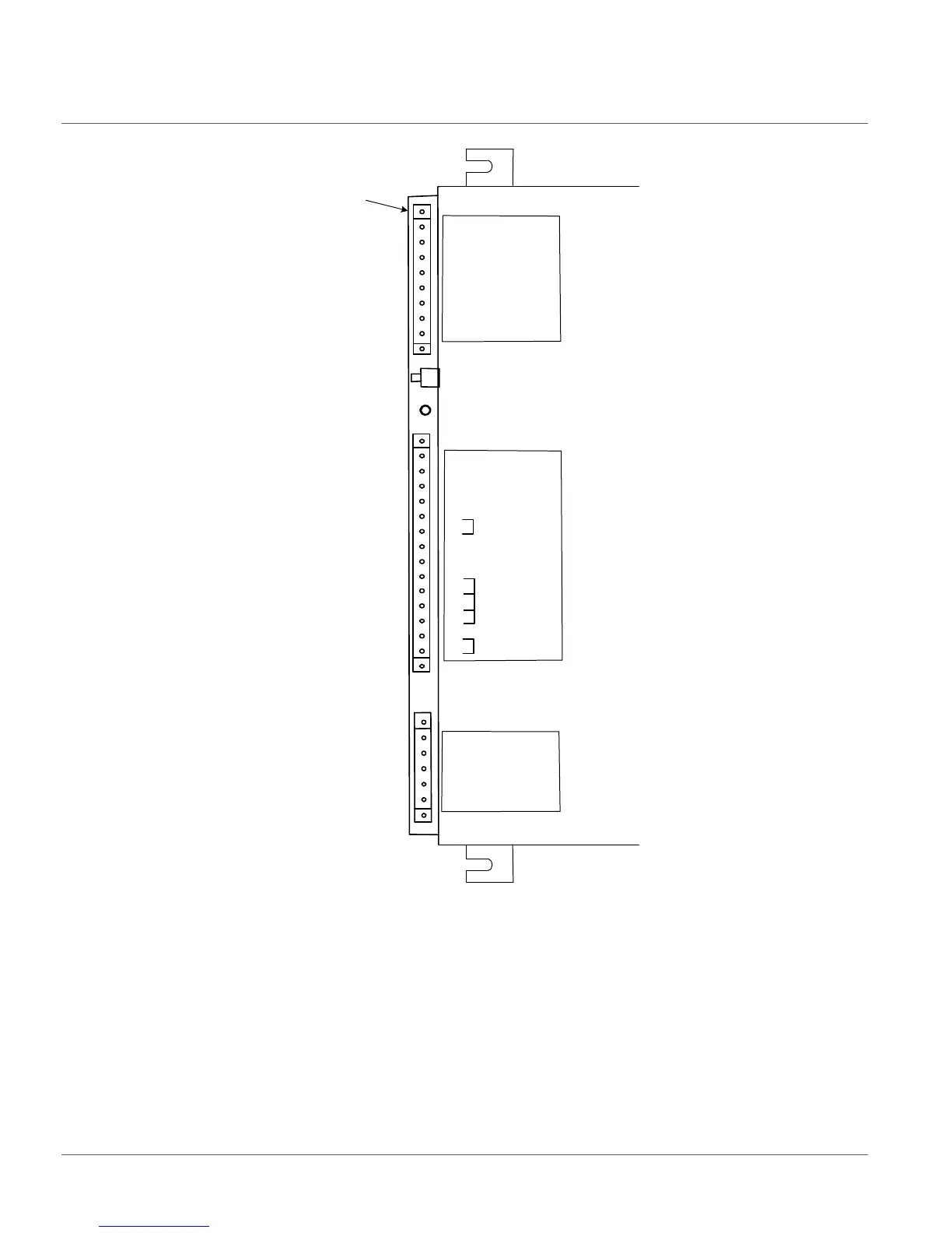
Figure 12: Connections to Uninterruptable Power Supply (UPS)
5.6 Connecting communication
Before connecting communication, check that the HW module has the correct
communication interfaces. The communication module is located on the left side of the
IED when viewing the case from the rear.
Connector W1
Battery Start
Status LED D21
Connector W3
1
2
3
4
EARTH
5
485 COM
- 485
+ 485
No Connection
L2 (neutral)
1
2
3
4
5
6
+ AUX12/24
7
8
L1
- AUX
+ 60VDC
60 Return
No Connection
No Connection
ALARM N/C
Connector W2
Heater 2
ALARM COM
1
2
3
4
5
6
7
ALARM N/O
8
9
10
11
12
13
14
+ BATTERY
- BATTERY
RETURN
+ BOOST
No Connection
Connect ground
to case screw.
Heater 1