*HQHUDOLQIRUPDWLRQ
1.4. Calibration scales and correct axis position
193HAC 16578-1 Revision: E
© Copyright 2003-2007 ABB. All rights reserved.
&DOLEUDWLRQVFDOHVPDUNV,5%
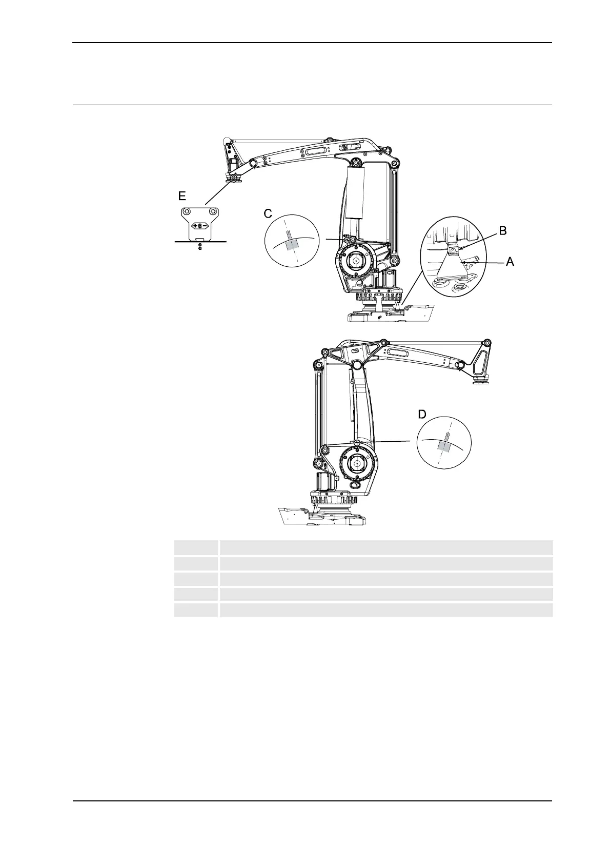
The illustration below shows the positions of the calibration marks on the robot.
xx0500002487
Calibration marks at axes 2 and 3
The calibration marks at axes 2, 3 and 6 shown in the figure above, consist of two single
marks that should be positioned opposite to one another when the robot is standing in its
calibration position. One of the marks is more narrow than the other and should be positioned
within the limits of the wider mark.
A Calibration plate, axis 1
B Calibration tab on robot
C Calibration mark, axis 2
D Calibration mark, axis 3
E Calibration plate and marking, axis 6
&RQWLQXHG
&RQWLQXHVRQQH[WSDJH