3UHSDULQJWKHHTXLSPHQW
2.3. Calibration of sensors (calibration pendulum) and Levelmeter 2000
333HAC 16578-1 Revision: E
© Copyright 2003-2007 ABB. All rights reserved.
&DOLEUDWLRQRIVHQVRUV
The procedure below details how to calibrate the sensors.
From RobotWare 4.0.110 (M2000) and 5.05 (M2004) calibration of the sensors is included in
the service routine. Follow the procedure below for earlier RobotWare releases.
$FWLRQ 1RWH,OOXVWUDWLRQ
1. Place the calibration plate on a steady and flat
foundation. Clean the calibration plate surface
with isopropanol.
Clean the three contact surfaces of the sensor
with isopropanol.
Fit the sensor in one of the two possible positions.
Shown in the figure 6HQVRUILWWHGWR
WKHFDOLEUDWLRQSODWHRQSDJH.
2. Press repeatedly the button ON/MODE until the
marker moves to the text SENSOR.
3. Press repeatedly the button ENTER.
4. Press repeatedly the button ZERO/SELECT until“
A” appears under the Port/Sensor.
5. Press the button ENTER and wait until “A” stops
flashing.
6. Press the button ON/MODE until the marker
moves to the text “ZERO”.
7. Press the button ENTER. The direction indicator
(+/-) and the last zero-offset will be displayed. Wait
a couple of seconds for the sensors to stabilize.
8. Press the button HOLD and wait until the marker
under ZERO starts to blink.
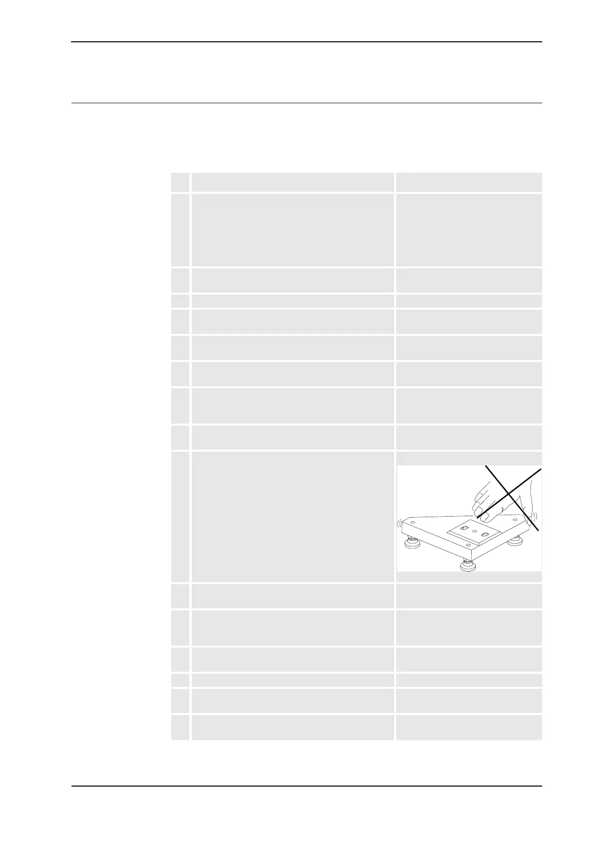
9. Remove the pendelum tool, turn it 180° and fit the
tool in the corresponding hole pattern.
1RWH'RQRWFKDQJHWKHSRVLWLRQRIWKH
FDOLEUDWLRQSODWH
Wait a couple of seconds for the sensors to
stabilize.
xx0300000207
10. Press the button HOLD and wait a couple of
seconds. The new zero offset will be displayed.
11. Press the button ENTER, now the sensor is
calibrated and should display the same value, but
with different direction (+/-) for the two positions.
12. Adjust the instrument as described in step 2- 5, to
read the sensor ”B”.
13. Repeat the actions described in step 6 - 11.
14. Adjust the instrument as described in step 2- 5, to
read the sensor “AB”.
15. Check the results. Detailed in section &KHFNLQJRI
VHQVRUVRQSDJH.
&RQWLQXHG