&DOLEUDWLRQ
3.2.5. Calibration sensor mounting positions, CalPend
3HAC 16578-1 Revision: E52
© Copyright 2003-2007 ABB. All rights reserved.
,5%,5%
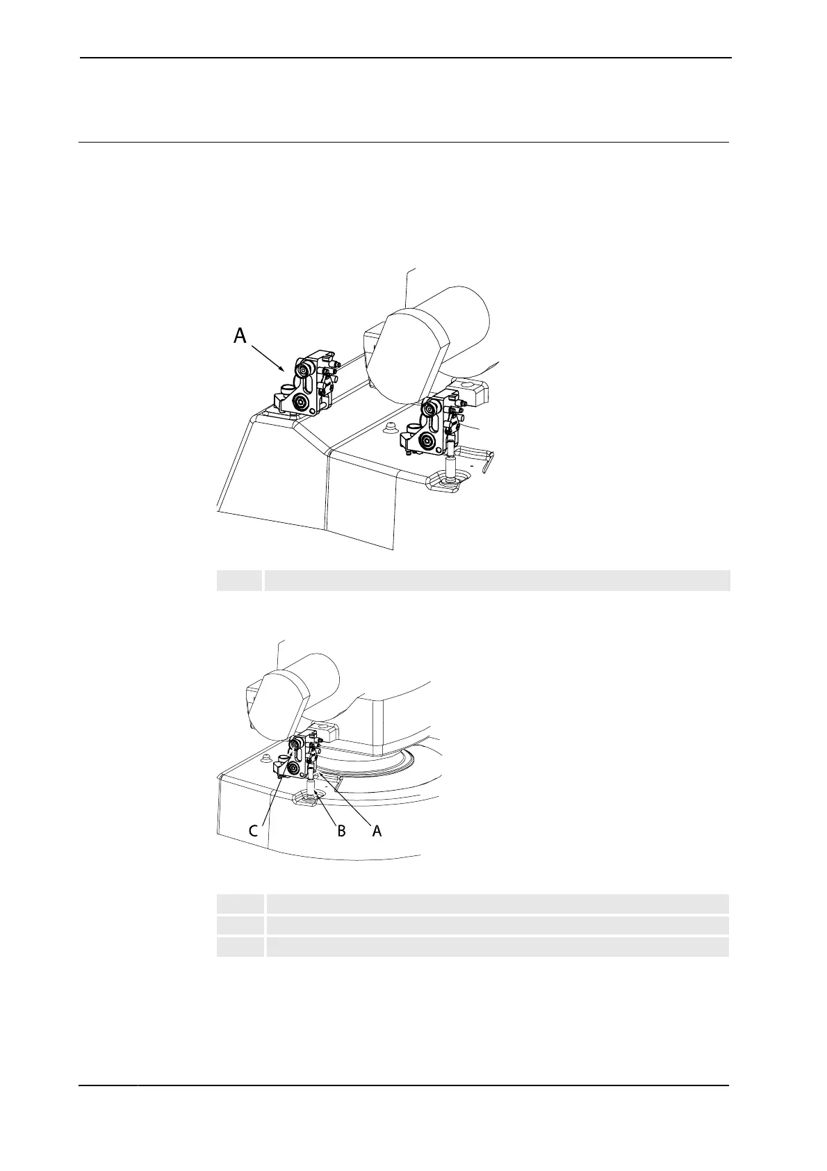
The illustrations below show the mounting positions and directions for both the reference
sensor and axis sensors on the robot. Notice that the pendulum is only fitted in one position
at a time (the pendulum is used as both a reference and a calibration sensor)!
Reference position IRB 2400, IRB 260
xx0200000250
Axis 1 IRB 2400, IRB 260
xx0200000251
A Calibration pendulum in reference sensor position
A Calibration sensor, axis 1
B Locating pin
C Calibration pendulum attachment screw
&RQWLQXHG
&RQWLQXHVRQQH[WSDJH