5
Operation
Emergency stop
Push the emergency stop button.
An actuating force of 22 ± 4 N is required, and the actuator travel is approximately 4 mm to
latch. Pull the button until the button is unlatched.
Key switch
The selector switch is safely activated when it is in the right position. The key can be taken out in both left and right
position.
NOTE: The keys for the selector switch is not individual coded.
LED indication
LED-indication is programmed individually in the PLC-programed according to the table below, depending on
variant.
LED indication on non-safe node:
LED indication on safe nodes:
Led Indication is programmed individually per function and per safe node in the PLC-program according to the
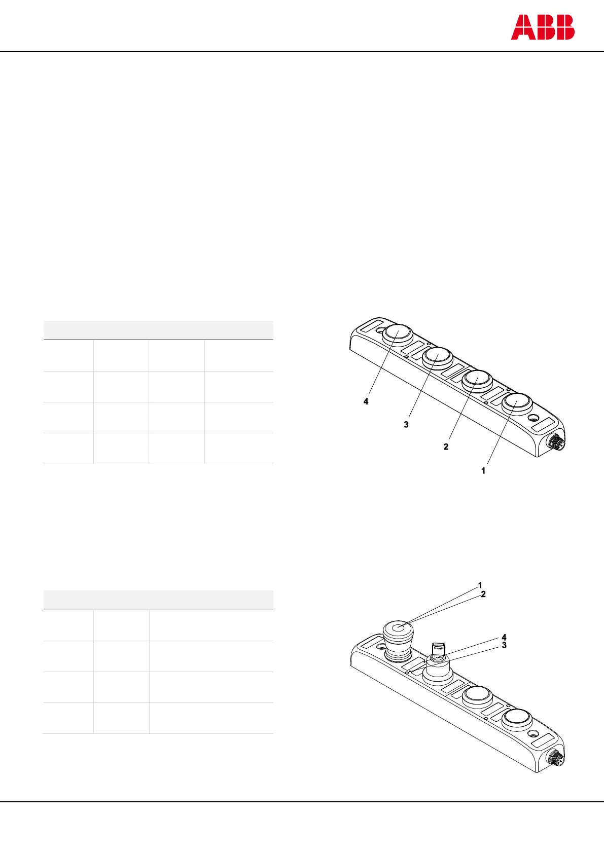
table below. The status of a push-button can be indicated by a central LED. If bit 1 and bit 2 both are set to 1 the
LED will be “off”. A key selector can be indicated by one LED to the right and one to the left. The picture illustrates
the position of the LEDs on a unit with both emergency stop and key selector. In this case they have on safe node
each.

 Loading...


