17
The secondary current of the current trans-
former is to be selected on the basis of the rated
current, 1 A or 5 A, of the relay energizing input
to be tested. The energizing inputs are specified
in chapter "Technical data" under the heading
"Energizing inputs".
≅
5A
1A
SPAJ 111 C
U2
U3
11
11
D
CBA
25
SGR/1
U3+
-
E
_
10 11 61 62 717270 7877 8180 6968 6665
SGR
7
5 6
8
3 2 4
SIGNAL1
TRIP2
TRIP1
26 27
IRFUaux
+
(
~
)
-
(
~
)
A
TIMER START
S1
L1
N
S2 L2 L3
BS START1
TIMER STOP
IRF
L1 L4
TS2
TS1
SGB
SS1
SS2
U1
5
4
I/O
t >>
t >
Io>
Io>>
73
74
75
START2
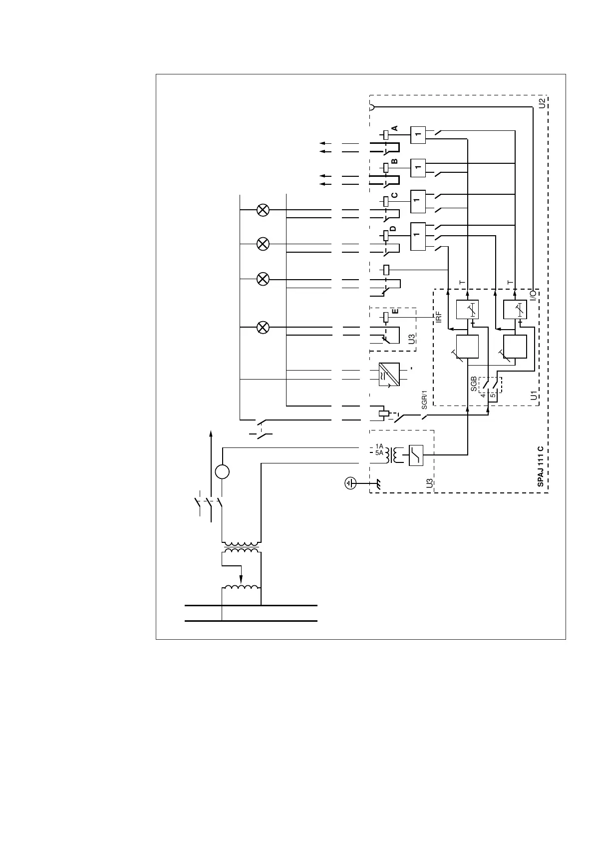
Fig. 7. Secondary injection test circuit for the earth-fault relay SPAJ 111 C.
When the test circuit has been completed and
the selector switches have been properly set, the
auxiliary voltage is connected to the relay. The
operation of the test circuit can be verified by
using a multimeter.


 To Next Page