19
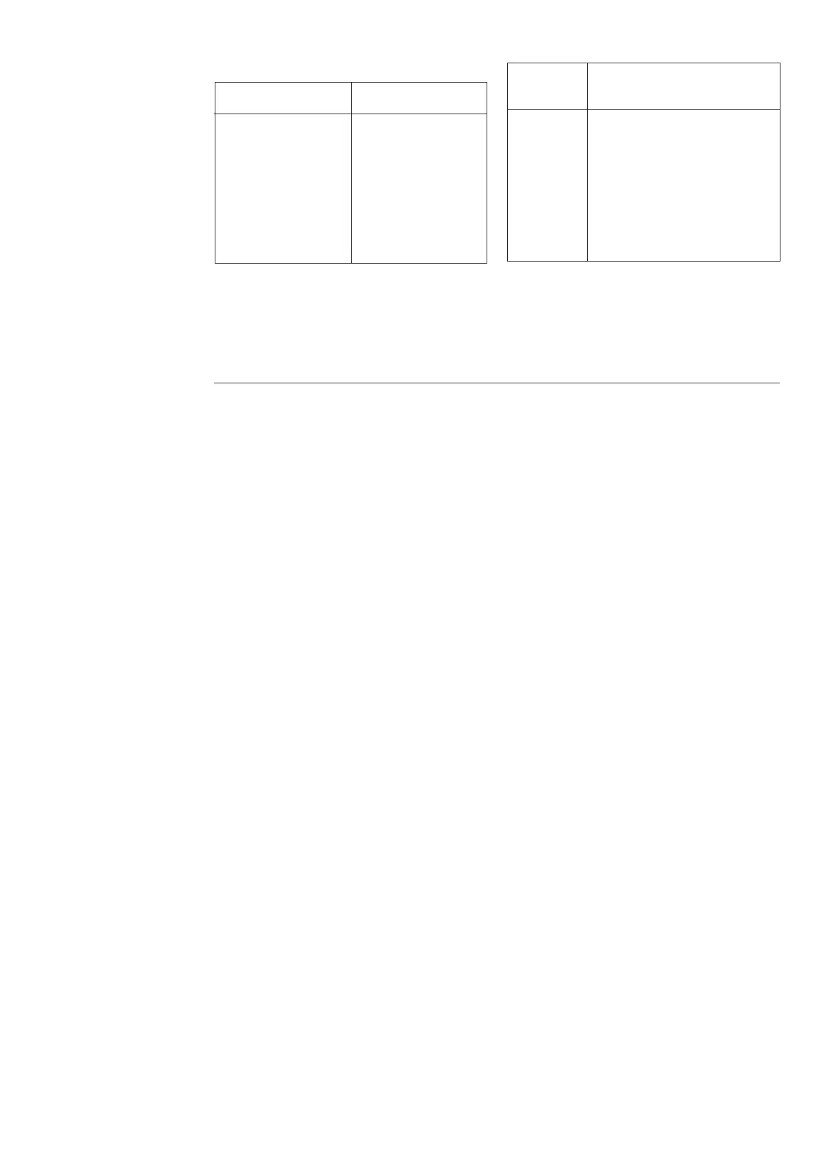
The following relay functions are obtained:
Output rel. Function
(terminals)
A (65-66) (Trip signal of the I
0
> stage)
B (68-69) Trip signal of the I
0
>> stage
C (80-81) Signal on tripping of the
I
0
>> stage (ind. L4)
D (77-78) Start signal of the I
0
>> stage
(ind. L3)
E (71-72) Self-supervision alarm (ind. L1)
F (74-75) (Start signal of the I
0
> stage)
Set the test current at 2 x the set start current of
stage I
0
>>. The clock is started by closing the S1
switch and stopped via contact 68-69, when
output relay B picks up.
Checking the high-
set stage I
0
>>
Set the switches of the SGR switchgroup as
follows before starting the test:
Switch Position
11
21
30
40
51
60
70
80
Note!
Heavy test currents may be connected to the
relay for a short time only. For technical speci-
fications for the energizing inputs, see chapter
"Technical data", section "Energizing inputs"
Checking the self-
supervision function
(IRF)
The self-supervision system and the function of
the IRF LED and the output relay E can be
tested in the Trip test mode described in manual
"General characteristics of C type relay mo-
dules". The operation of output relay E is indi-
cated by L1.


 To Next Page