TEIP11, TEIP11-PS I/P SIGNAL CONVERTER | OI/TEIP11/TEIP11-PS-EN REV. M 11
6 Installation
Mounting
Note
Installation location requirements
Prior to installation, check to make sure that the TEIP11 and
TEIP11-PS I/P signal converters meet the measurement and
safety requirements applicable at the installation location (see
Additional documents on page 16).
Only qualified specialists who have been trained for these tasks
are authorized to mount and adjust the unit, and to make the
electrical connection.
When carrying out any work on the device, always observe the
local accident prevention regulations and the regulations
concerning the construction of technical installations.
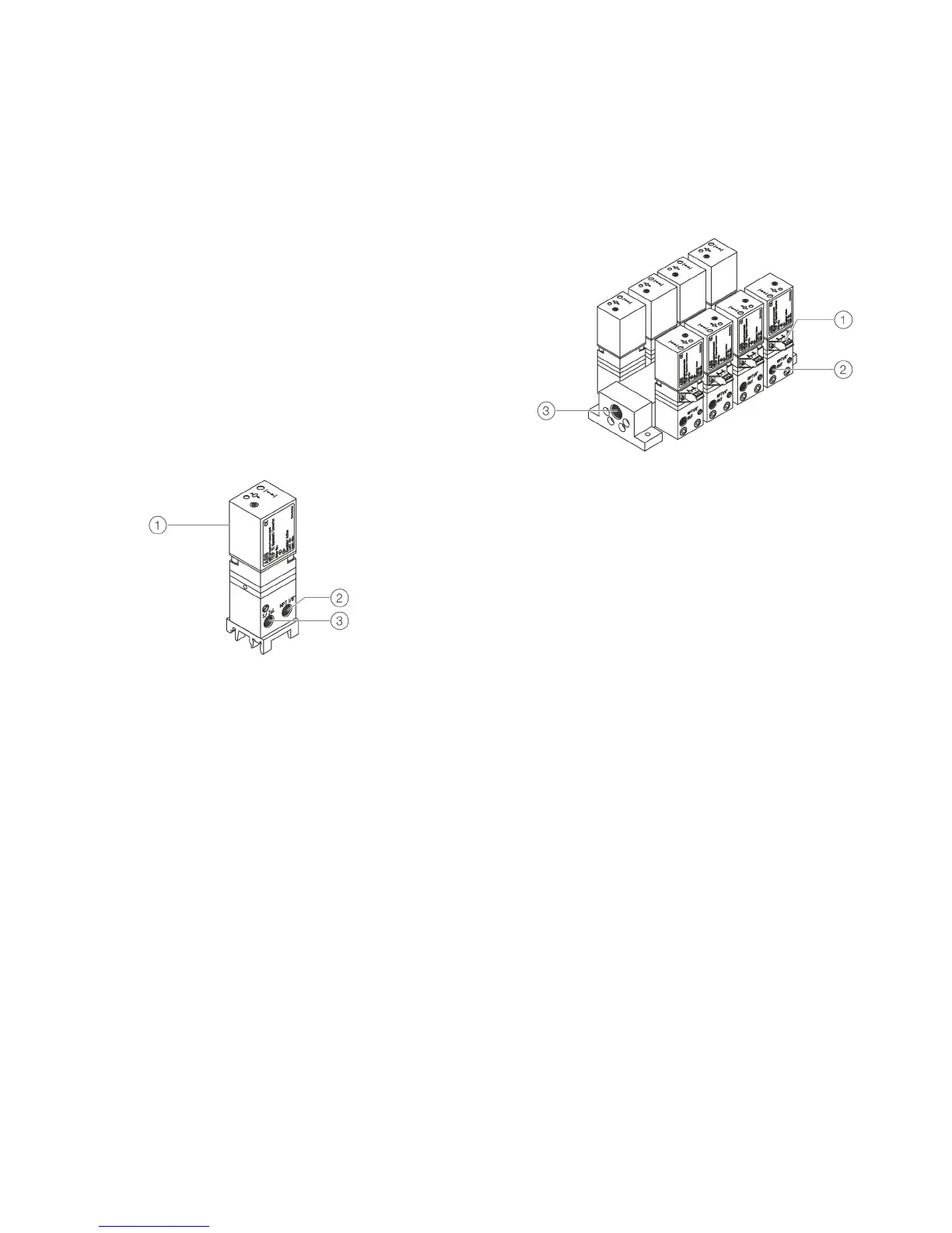
Control room housing unit for rail mounting
This model is snap-mounted on a DIN top-hat rail.
1 Terminal for signal input
(covered)
2 Output
3 Supply air connection
Figure 4: Control room housing for rail mounting
Design
The TEIP11 and TEIP11-PS I/P signal converters have a special
mounting base which fits all mounting rails in accordance with
EN 50022 - 35 × 7.5, EN 50045 - 15 × 5, and EN 50035 - G32.
Installation instructions
For mounting rails that are mounted in a vertical position, the
electrical connection for the device should preferably face to the
left.
For mounting rails that are mounted in a horizontal position, the
electrical connection for the device should preferably be facing
up.
Control room housing unit for block mounting
For this design, a special connection block is used to mount the
unit.
1 Terminal for signal input 2 Output
3 Supply air connection
Figure 5: Control room housing for block mounting
Design
The connection block is designed for mounting a maximum of
4 I/P signal converters. The connection blocks can be expanded
to units of 2, 3 or 4 blocks to create block units of 4, 8, 12 or
16 I/P signal converters.
Installation Material
The material for forming the block units is delivered separately
for self-installation; in addition to the connection blocks, it
includes the necessary screws and gaskets (O-rings).
Supply air connection
The supply air connection for the connected devices is provided
via a central connection block. The connection block features a
non-return coupling for each individual I/P signal converter. This
allows connection sites to remain unused, and individual I/P
signal converters can be dismounted or mounted during
operation.