TPU2000/2000R Modbus/Modbus Plus Automation Guide
15
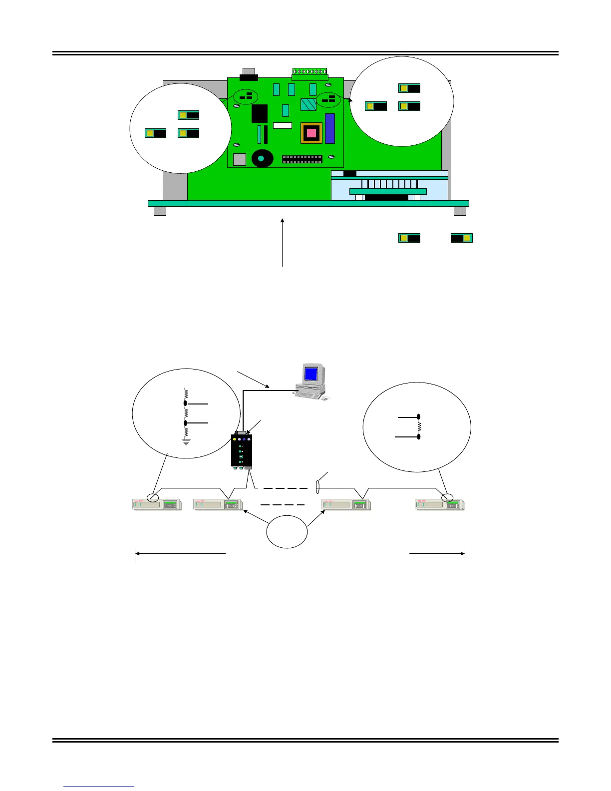
Jumper OUT Jumper IN
Top View
Component Location with Unit Removed From The Case (Top View)
J8
J7 J6
OUT IN
OUT IN
Option 8
Board
Option 4 or 8
Board
J18
J17 J16
OUT IN
OUT IN
Option 8
Board
Figure 3-5. Location of RS485 Resistor Configuration Jumpers in the TPU2000R
Unicom Physical Interface
Converter Switch Settings
:
- DTE
- RS232-RS485
- 19200 Baud
- HD
Cable “A”
See Attached Diagram
E
C
E
C
E
C
32 Devices and 3000 Feet Maximum loading and distance.
E
C
Unit 1 Unit 2 Unit 30 Unit 31
Three-wire cable with
shield. Cable “B” - See Attached Diagram.
End Unit Inline Unit Inline Unit End Unit
Jumpers
J6, J7, J8
“OUT”
+ 5 V
120 Ohms
470 Ohms
470 Ohms
Jumper J8 “IN
Jumper J 7 “IN”
Jumper J6 “IN”
TX/RX +
TX/RX -
Topology Diagram for RS485 Multi-Drop Architecture - if jumpers are
inserted on end units providing for proper termination.
* See Note A.
* Note A - Following Cable Recommended
Alpha # 58902
Belden # 9729, # 9829
Carol #58902
120 Ohms
Jumper J8 “Out”
Jumper J6 “IN”
TX/RX +
TX/RX -
Jumper J 7 “Out”
Figure 3-6. RS485 Topology Configuration for the TPU2000R