TPU2000/2000R Modbus/Modbus Plus Automation Guide
31
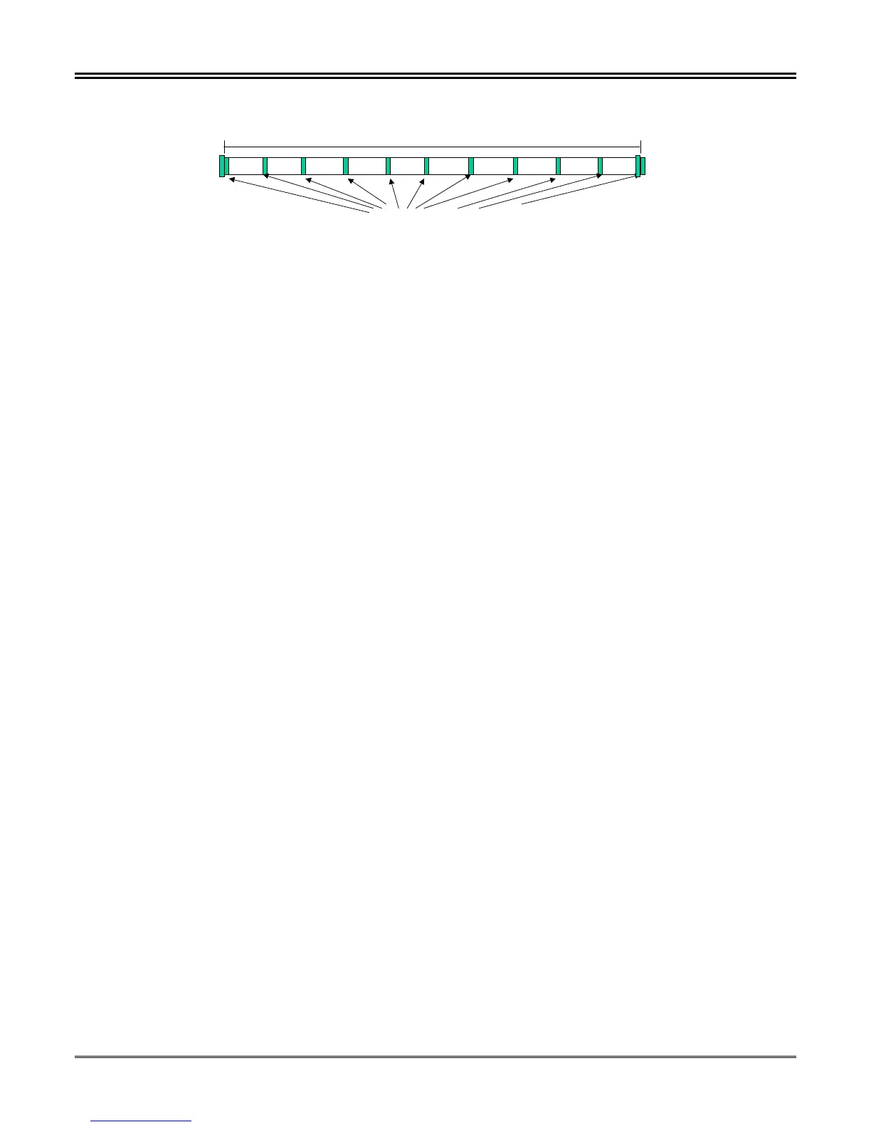
Seconds Minutes Hours Days
Control Functions
Straight Binary Time of Day
0 10 20 30 40 50 60 70 80 90 0
Marker Pulses every 10 mS for an 8 mS duration
1 Second Frame in 10 mS increments
Figure 4-10. IRIG B Frame Construction
IRIG B is defined for code format sets identified by a three digit format number. Permissible format numbers for
the IRIG B subsets are:
IRIG B XYZ Where:
The first field "X" identifies the encoding type of the IRIG B signal. DPU/TPU/GPU products support Pulse Width
Code (X= 0), whereas, REL 3XX products having an IRIG B PONI Card support Pulse Width Code and Sine
Wave Amplitude Modulated, and REL5XX products support Sine Wave Amplitude Modulated IRIG. Manchester
Modulated code was added in IRIG Standard 200-98 Dated May 1998. It is not supported in the ABB protective
relay products which are IRIG B capable.
The second field "Y" determines if a carrier is included within IRIG B Data format.
The third field "Z" determines if a combination of the BCD time/Control Function/Straight Binary Time is included
within the IRIG B time frame. The inclusion or exclusion of any of the fields may cause errors in receivers not
designed for the field’s inclusion/ exclusion.
The following combinations may seem daunting, but only a subset of the listed formats are actually defined within
the specification.
IF X =
0 = Pulse Width Code
1 = Sine Wave Amplitude Modulated
2 = Manchester Modulated Code
IF Y =
0 = No Carrier
2 =1Khz , 1mS
3 =10Khz, 0.1 mS
4 =100 Khz, 10 mS
5 =1Mhz, 1mS
IF Z=
0 =BCD Time,Control Function, Straight Binary Seconds
1 =Binary Coded Decimal Time, Control Function
2 =Binary Coded Decimal Time
3 =Binary Coded Decimal Time, Straight Binary Seconds
For the TPU/GPU/DPU2000/2000R products, IRIG B 000 and 002 formats are supported. Consult the IRIG B
generator manufacturer so that the correct IRIG B code format is supplied to the receiving devices.
Hardware Configuration