12 OI/TTR200-EN Rev. B | TTR200
7.2.2 Pin configuration
Resistance thermometers (RTD) / resistors (potentiometers)
Fig. 9
A Potentiometer, four-wire circuit B Potentiometer, three-wire circuit C Potentiometer, two-wire circuit D RTD, four-wire circuit
E RTD, three-wire circuit F RTD, two-wire circuit G Voltage measurement H Thermocouple I Terminal 11: Measurement of the
4 … 20 mA output current without opening / interrupting the current loop J Without function 1 – 4 Sensor connection (from measuring
inset)
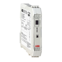
— PWR / green LED: supply voltage display
— ERR / red LED: sensor, sensor lead & unit fault signaling
— DIP switch 1: on -> hardware write protection enabled
— DIP switch 2: without function
Change from one to tw o columns
A10203
12 ... 30 / 42 V DC
+
-
4 ... 20 mA
TTR200
+
11
PWR
ERR
OFF ON
1
2
-
12 3
4
5
6
+
-
+
-
4
JJ
2
2
1
11 1
4
3
3
3
3
2
33
22
k
J
2
1
3
J
1
3
ABC D E F GH
J
I

 Loading...