Do you have a question about the ABB 4600 Series and is the answer not in the manual?
Verifies the instrument's model number for correct identification.
Guidelines for optimal placement to ensure safe and reliable operation.
Instructions for physically attaching the instrument to walls or pipes.
Procedures for safely accessing the instrument's connection points.
General guidelines for wiring, earthing, and cable routing.
Specific wiring diagrams and terminal assignments for wall/pipe models.
Specific wiring diagrams and terminal assignments for panel models.
How to configure the instrument for different supply voltages.
Explanation of the instrument's digital display layout and information.
Details on the membrane switches and their operational logic.
Steps for powering up and initiating the instrument.
Description of the main display screen during normal operation.
Lists and explains potential error messages shown on the display.
Guide for calibrating the instrument using a single calibration point.
Guide for calibrating the instrument using two calibration points.
Procedure for using pre-defined calibration settings.
How to enter the security code to access protected settings.
How to choose the display language for the instrument.
Configuration options for thermocouple type and temperature settings.
Configuration of alarm set points, retransmission, and output types.
Lists the necessary tools and equipment for electrical calibration.
Steps to prepare the instrument and equipment for calibration.
Detailed procedure for performing electrical calibration of the instrument.
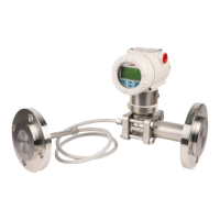
The ABB 4600 Series Oxygen Transmitters, specifically models 4681 and 4686, are designed for continuous monitoring of oxygen content in applications utilizing 'in situ' ZGP2 probes. These instruments offer a comprehensive set of features for operation, programming, and maintenance, ensuring accurate and reliable oxygen measurement.
The primary function of the 4681 and 4686 Oxygen Transmitters is to continuously monitor and display the percentage of oxygen, cell millivolts, or cell temperature. This allows for real-time assessment of oxygen levels within a process. The transmitters are designed to work in conjunction with ZGP2 probes, which provide the 'in situ' measurement.
A key feature is the retransmission output facility, which allows measured %O₂ values to be sent to remote equipment. The range of retransmitted values is configurable from 0 to 25% O₂, providing flexibility for various control systems.
For remote alarm indication, the transmitters are equipped with two relay outputs. These relays can be programmed to activate when the oxygen level exceeds or falls below a predefined set point. The second alarm relay can also be configured as a 'general alarm,' which activates in the event of an instrument or system fault, offering an additional layer of safety and operational awareness.
An optional external reference air unit can be used to supply reference air to the ZGP2 probe. If this unit is not specified, reference air must be sourced from an alternative supply, ensuring the probe functions correctly.
The transmitters feature a user-friendly interface with four tactile membrane switches and a digital display on the front panel. Two LEDs provide local alarm indication, making it easy to quickly identify alarm conditions.
In normal operation, the upper display line shows the actual measured values, such as % oxygen, temperature, or cell millivolts. In programming mode, this display is used to show programmable parameters. The lower display line provides associated units and other programming information, guiding the user through various settings.
Programming and setup of alarm, retransmission, and calibration parameters are performed in programming mode. Key parameters are protected by a five-digit security code, preventing unauthorized access and accidental changes.
The instrument offers different calibration sequences: single-point, two-point, and preset calibration.
The language of the display text can be selected from English, German, French, or Spanish, enhancing usability for a diverse range of operators.
Users can also configure thermocouple type (K, R, S, B, or NONE) and, if no thermocouple is used, set a preset process temperature.
Output settings are highly configurable, including alarm actions (input above/below set point, general alarm), alarm set points, and retransmission type (4-20mA, 0-20mA, or 0-10mA). The retransmission output can be set to either logarithmic or linear, depending on the application's needs. The retransmission zero and span values are also adjustable.
A "Hold Outputs" feature allows the retransmission and alarm outputs to be held during test gas calibration sequences, preventing inadvertent operation. A "Test Retransmission" function enables the instrument to transmit a test signal (0, 25, 50, 75, or 100% of the retransmission range), aiding in system verification.
The manual emphasizes several aspects related to installation and electrical connections that contribute to the long-term reliability and maintainability of the device.
For mechanical installation, siting requirements include mounting the instrument in a location free from excessive vibration, harmful vapors, and dripping fluids. It is recommended to mount the instrument at eye level for an unrestricted view of the front panel displays and controls. The enclosures are rated IP66, indicating protection against dust and powerful water jets, which is crucial for maintaining internal components in harsh industrial environments.
Electrical connections are detailed with clear instructions for accessing terminals on both wall-/pipe-mounted and panel-mounted instruments. Important safety warnings are provided, such as switching off power before making connections and ensuring proper earthing to prevent RFI interference and ensure personnel safety.
Guidance on cable routing, cable glands, and conduit fittings ensures moisture-tight connections and separation of signal and power cables, minimizing interference and potential damage.
Relay contact protection and interference suppression are critical maintenance considerations. The manual advises fitting arc suppression components (resistor/capacitor networks for AC or diodes for DC applications) to prevent contact erosion and RFI, which can lead to instrument malfunctions. Specific part numbers and troubleshooting steps are provided for these components.
The selection of mains voltage is also covered, with clear instructions and diagrams for adjusting the voltage setting (115V or 230V) for both wall-/pipe-mounted and panel-mounted models.
An appendix on electrical calibration outlines the equipment required and preparation steps for performing an electrical calibration. This procedure, typically performed by the company prior to dispatch, is intended for situations where the instrument's accuracy is suspect and suitably calibrated test equipment is available. It involves setting specific millivolt sources for cell and temperature simulation, measuring ambient temperature, and adjusting retransmission zero and span to ensure accurate output signals. This detailed calibration process ensures the instrument maintains its accuracy over time.
| Manufacturer | ABB |
|---|---|
| Category | Transmitter |
| Type | Pressure Transmitter |
| Operating Temperature | -40 to 85 °C (-40 to 185 °F) |
| Communication Protocol | HART |
| Series | 4600 |
| Output | 4-20 mA HART |
| Process Connection | 1/2 in. NPT |
| Electrical Connection | 1/2" NPT |
| Housing Material | Stainless steel |
| Diaphragm Material | 316L stainless steel |
| Protection Rating | IP67, NEMA 4X |
| Storage Temperature | -40 to 85°C (-40 to 185°F) |