8 UNIGEAR ZS2 INSTALLATION, OPERATION AND MAINTAINANCE INSTRUCTION MANUAL
—
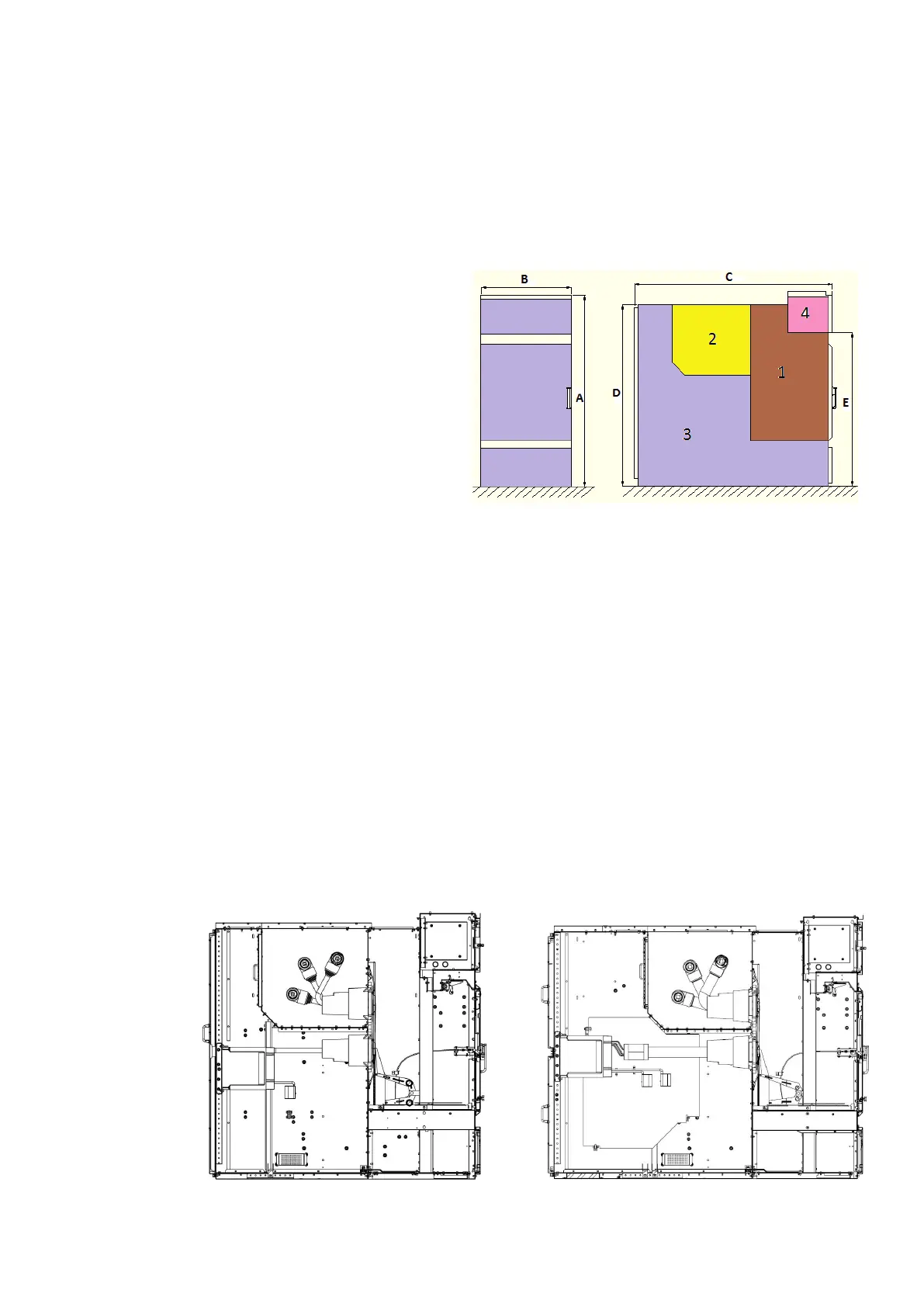
4. Switchgear design and equipment
4.1 Basic structure and variants
The basis for UniGear ZS2 switchgear is
an incoming or outgoing feeder panel
with circuit breaker. It is divided into
circuit breaker compartment 1, busbar
compartment 2, cable compartment 3,
low voltage compartment 4 for
secondary equipment. Apart from this,
there are variants for various operating
needs. Pictures in Fig. 3 to Fig. 12 show
examples of possible configurations
of a switchgear including electrical
equipment.
For busbar sectionalizing, two
switchgears are necessary, a coupling
switchgear with withdrawable circuit
breaker part and a bus riser switchgear
(may be with busbar metering and
earthing). In switchgear without busbar
sectionalizing, a direct bar connection
between the busbars
will be established. Further details about
installation and equipping the
switchgear can be obtained from
relevant order specific documents.
1. Circuit breaker compartment
2. Busbar compartment
3. Cable compartment
4. Low voltage compartment
—
Figure 2 - Basic Structure of ZS2
—
Figure 3 - Cross section of feeder unit 36kV, 630A -
1250A, 31.5kA, 2200 mm depth
—
Figure 4 - CCross section of feeder unit 36kV, 1600A/2000A/2500A,
31.5kA, 2600 mm depth

 Loading...


