12
200
375
85 90
43.5
43.5
158.5
248
Ø12.5
600
1037
189
78.5
958.5
200
500
147.5 152.5
43.5
43.5
158.5
248
Ø12.5
600
1037
189
78.5
958.5
100
150
25
25
158.5
248
Ø12.5
600
1037
4.3.2 Cable passage hole dimensions and fixing points
The following figures show the locations and sizes of the cable
passage holes under the different units. These holes must be
made before installation of the switchgear. The figures also
Figure 27. 375 mm wide units Figure 28. 500 mm wide units
show the switchgear fixing points. There is one fixing point in
each corner of the unit (4 per unit). Units without cable entry
have dimensions and fixing points according to the width of the
unit 10 mm anchoring bolts can be used for fixing.
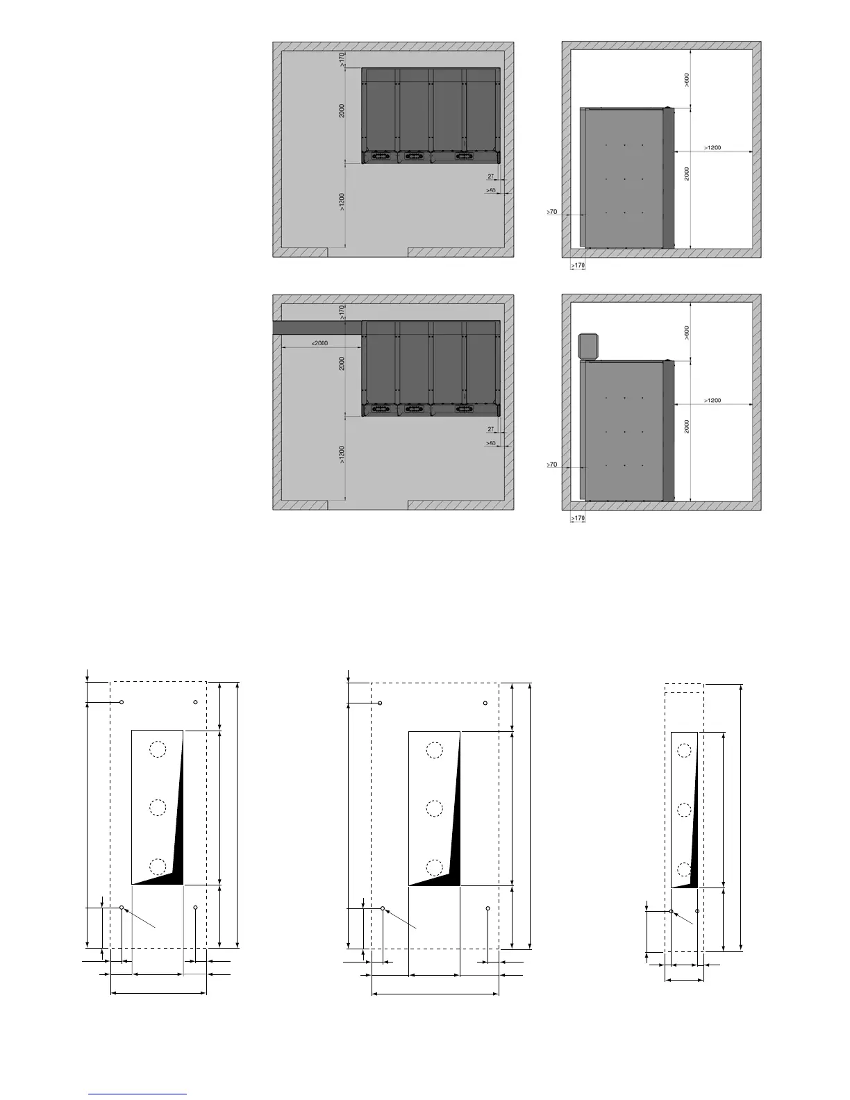
Figure 25. Minimum distances to
installation room wall with gas
absorbers.
Class ALFR.
Figure 26. Minimum distances to the
installation room walls with gas vent
ducts.
Class AFLR.
Switchgear supplied with 1 m long
external duct.
Figure 29. 190 mm wide for
RLC/RRC unit (for SBR only)