34
1ZSE 5492-115 en, Rev. 5
fm_00077
fm_00078
Appendix A
3 Welding and mounting instruction
Install the on-load tap-changer in the tank and bolt it to the tank with the gasket between
the tank and the on-load tap-changer. For on-load tap-changers BIL 550 and BIL 650,
install shields at the same time as shown in Fig. A5.
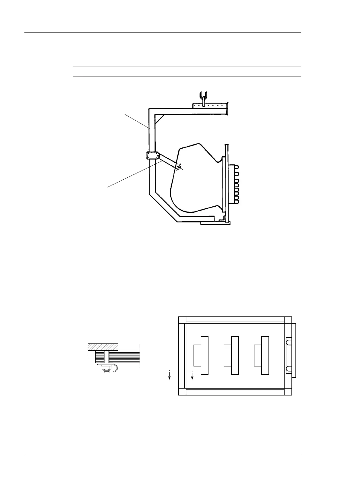
When the on-load tap-changer is xed to the tank, remove the lifting yoke and tighten the
nuts by torque 42 Nm (oil-greased nuts, M12). Remove the glass-bre stud used as trans-
port support. Finally, install the support for the geneva gear as shown in Fig. A7.
CAUTION
The link according to Fig. A4 must be attached before taking away the support.
View A – A
Link
Fig. A5. Shield installation (only on on-load tap-changers BIL 550 and BIL 650).
Lifting yoke
Fig. A4. Lifting after raising.