16
1ZSE 5492-115 en, Rev. 5
fm_00071
4 Installation on the transformer
4. Installation on the transformer
CAUTION
The on-load tap-changer must not be included in the drying process of the transformer.
The on-load tap-changer is either bolted or welded to the transformer tank, see
section 4.1.
NOTE: In the event of the on-load tap-changer being delivered without a tank, the
transformer manufacturer has to make the tank and mount it onto the transformer
tank; or make the on-load tap-changer tank integrated with the transformer tank.
Appendix A includes a welding and mounting instruction. In this case, continue with
section 4.2 directly.
4.1 Attaching the on-load tap-changer to the transformer
4.1.1 Welding
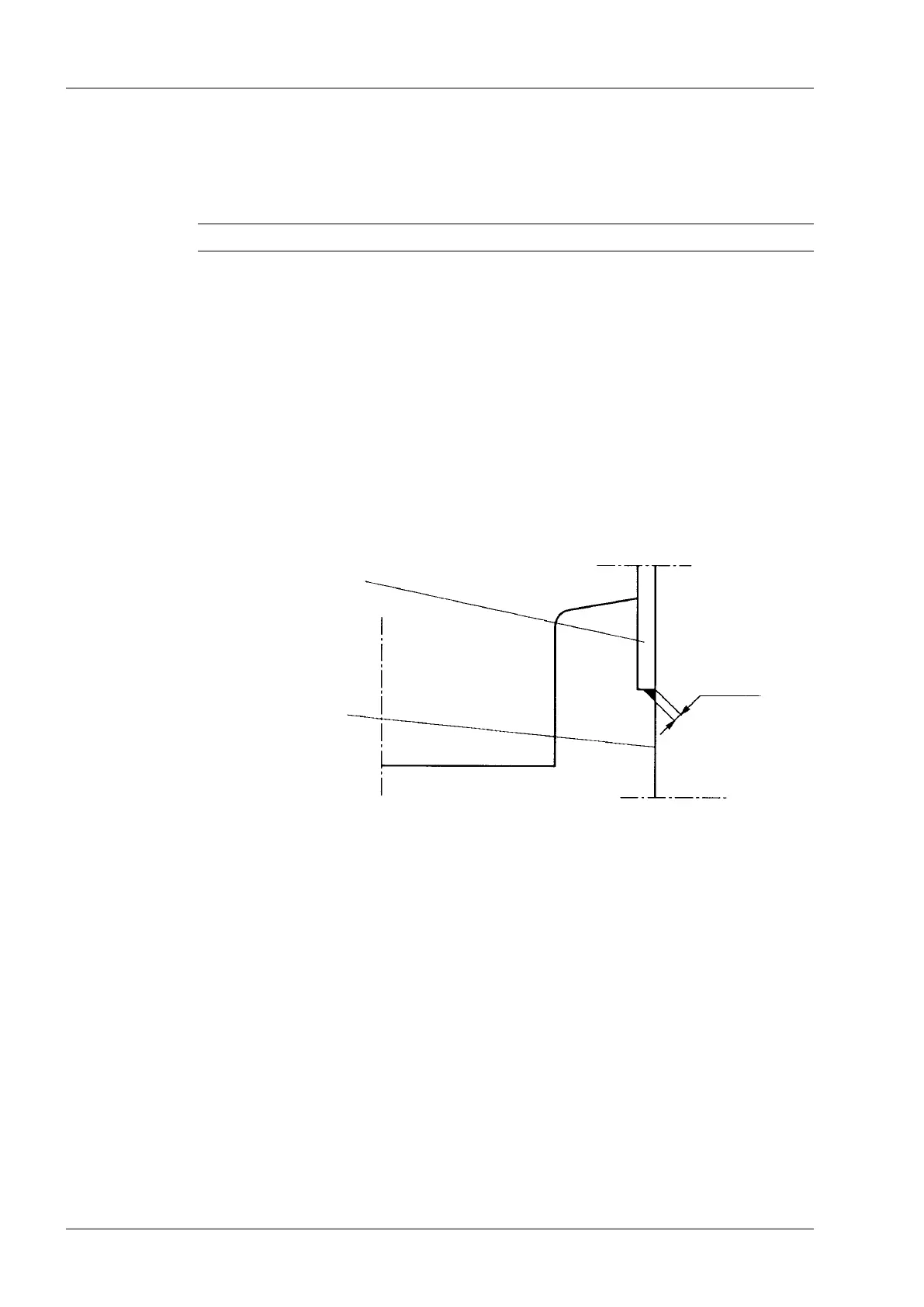
For welding the on-load tap-changer to the transformer tank, use llet weld with a ≥ 4 mm
(Fig. 6).
4.1.2 Bolting
A set of cork-rubber gaskets is provided to seal against the transformer tank.
When you install the on-load tap-changer, the gasket should be glued as described below.
Tighten the bolts by approximately 90 Nm torque.
Ensure that the surfaces being in contact with the gaskets are clean and free from grease
and oil.
After cleaning, stick the gaskets to the transformer tank ange (Fig. 7) with ABB glue
13401-608, by brushing glue on both the gasket and the ange.
On-load tap-changer
ange
a ≥ 4 mm
Transformer tank
Fig. 6. Welding detail.