15
VSC7
VSC12
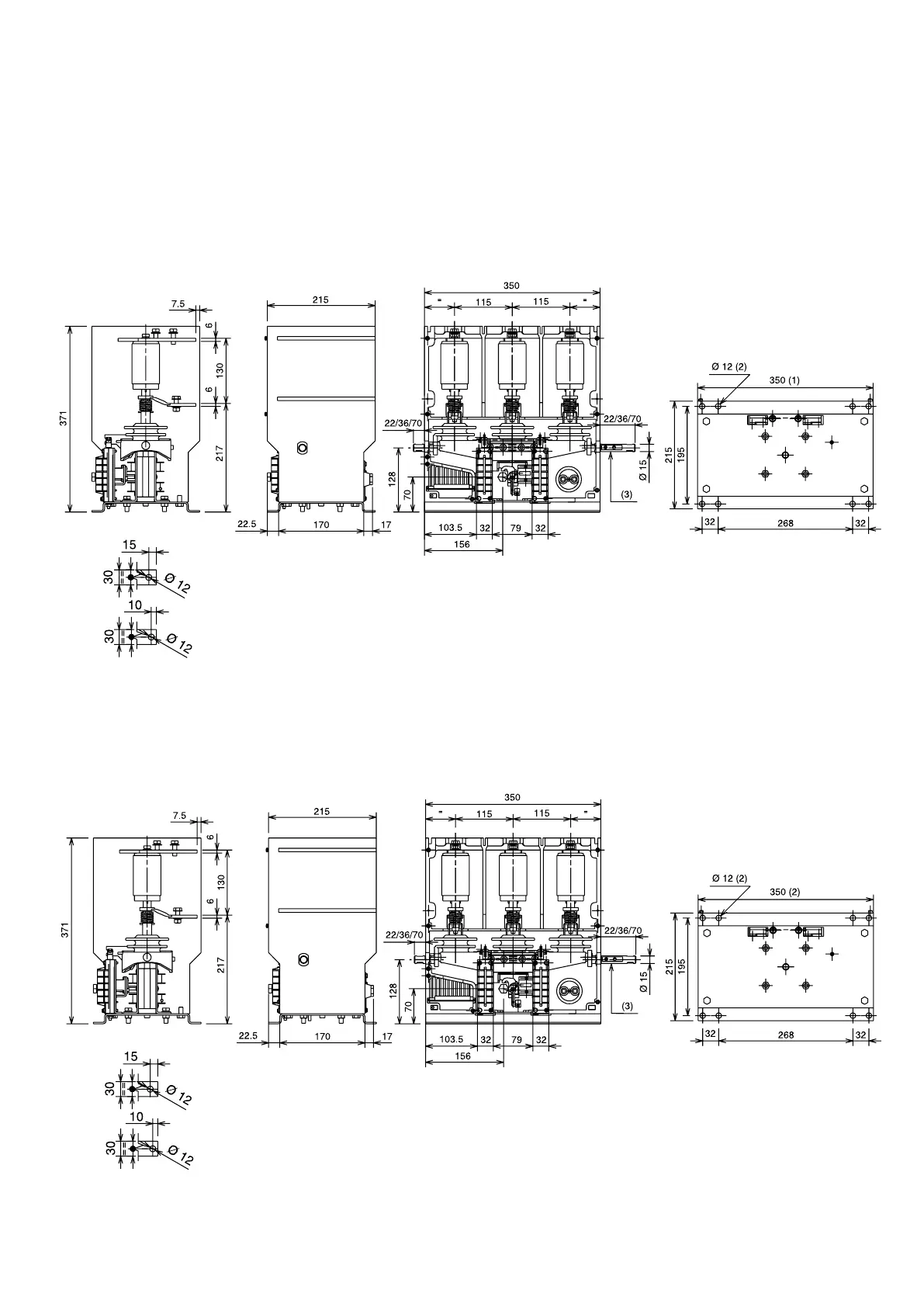
5.5. Overall dimensions
5.5.1. VSC fixed contactor
Fortheoveralldimensionsanddistancesbetweenfixingholes,refertofigure4a.
Inanycase,avoidstressingthesupportingstructureofthecontactor:ifnecessary,arrangeslotsinthefixingareatofacilitate
correct positioning of the apparatus.
The assembly positions can be selected between the two shown in figure 4b.
Fig. 4a
(1) Thewidthofthecontactorvariesbasedonthepresenceoftheinterfacing
shafts.
(2) Holeforearthingthecontactor
(3) Themaximum
torquewhichcanbeappliedtotheinterfacingshafts(right
and left) is 2 Nm. The rotation angle is approximately 10°.
(1) Thewidthofthecontactorvariesbasedonthepresenceoftheinterfacing
shafts.
(2) Holeforearthingthecontactor
(3) Themaximum
torquewhichcanbeappliedtotheinterfacingshafts(right
and left) is 2 Nm. The rotation angle is approximately 10°.
NEPSI.COM - Northeast Power Systems. Inc.

 Loading...


