40
69
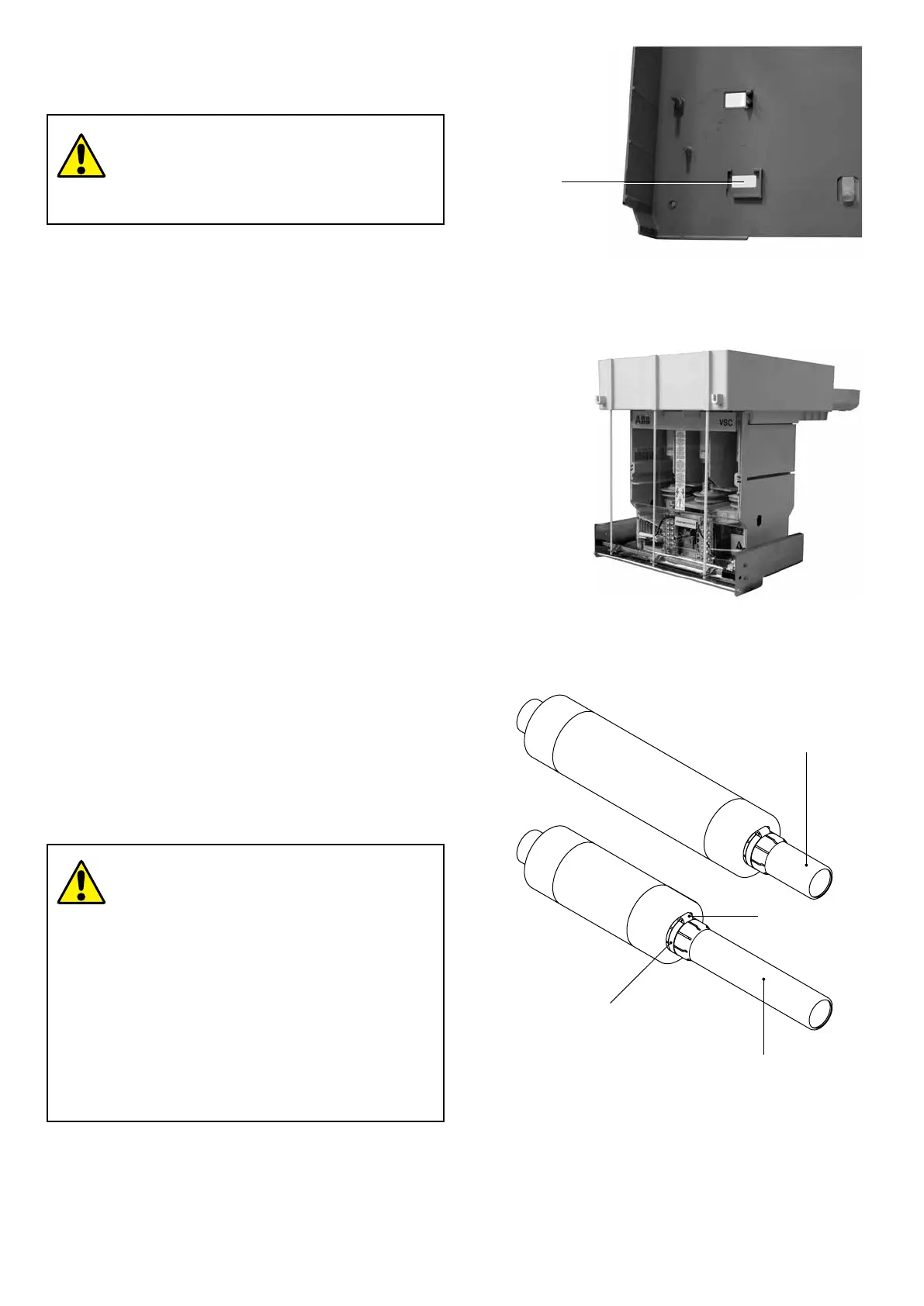
A
B
46
45
48
47
Fig. 18d
Fig. 18e
Fig. 19a
7.8. Replacement of the contactor
fuses
Check that the rated normal current of the
fuses to be installed corresponds with the
value indicated on the nameplate on the rear
of the fuseholder.
Fuses according to DIN Standards
a) Mounting the adapters (fig. 19a)
The fuseholder is designed to take fuses with a length of 442
mm.Forsmallersizes,twoadaptersarerequired:
– Adapter(45)forfuseswithalengthof192mm(A)
–Adapter(46)forfuseswithalengthof292mm(B).
Select the type of adapter in relation to the type of fuse to be
used,andinsertitfullyoverthefusecontact,oppositetothe
one of the striker.
Tightenthesteelband(47)andfullytightenthescrew(48).
Todismantle,proceedinreverseorder.
The same instructions are given in the Kit sheet put in the
adapter packing.
b) Dismantling the fuses (fig. 19b)
Openthelockingrings(49)(fig.19b)movingtheminthe
directionshownbythearrowsusingthetool(50),andremove
thefuseusingthespecialtool(50).
c) Mounting the fuses (fig. 19c)
Openthelockingrings(49)movingtheminthedirection
shownbythearrowsusingthetool(50)(fig.19b),fullyinsert
the fuses with the contacts fitted with striker on the opposite
side to the isolating contacts of the contactor. Close the
lockingringsagain,movingthemintheoppositedirectionto
the opening one.
Fuses according to BS Standards.
• Check that the rated normal current of the
fuses to be installed corresponds with the
value indicated on the nameplate on the
rear of the fuseholder.
• When tightening the screws, do not
force the connections (25 Nm maximum
tightening torque).
• Fuse mounting and dismantling must only
be done with the adapter (if required)
already mounted on it.
• Only use the material specified, provided
by ABB, for assembly.
NEPSI.COM - Northeast Power Systems. Inc.

 Loading...


