43
60
61
61
7.10. Putting the contactor back into
service
7.10.1. Mounting the shield and insulating guard (fig. 18)
Repositiontheprotection(1)(fig.18b),repeatingthe
operations indicated in par. 7.7.2. in reverse order.
Remounttheshield.Checkthattheimpulsecounter(14)(fig.
18c)insertsitselfintothespecialseat(69)(fig.18d)andfixthe
shield with the screws (70) and DIN washers (71) (fig. 18a).
7.10.2. Checking apparatus functions
Rackthecontactorintotheenclosure,workingasindicatedin
par. 6.
Inthe“isolatedfortest”position,checkthecorrectnessand
functionality of the contactor “open/closed” signalling by
carrying out a few operations.
7.11. Checking the degree of vacuum of
the interrupter
This test is not required for normal maintenance. Should
itbecomenecessaryforextraordinarymaintenance,carry
out the test on the interrupter without dismantling it from
thecontactorandusetheVIDARtester,oftheProgramma
ElectricGmbH,BadHombergv.d.H.company,forthe
vacuum test.
Tocheckthevacuumairtightnessoftheinterrupter,prepare
the following VIDAR tester test values:
Contactor rated voltage DC test voltage
7.2 kV
16 kV
12 kV
22.5 kV
Thetestmustalwaysbecarriedoutwiththecontactoropen,
with the contacts at the nominal distance.
Procedure for testing the vacuum of the interrupter of the
contactor poles:
– turn off the power and make the working area safe according
to the safety regulations of the IEC/DIN VDE standards;
– open the contactor;
– ground a terminal of each contactor pole;
– connect the ground terminal of the VIDAR tester to the
structureofthecontactor(groundingpointofthecontactor);
– connect the high voltage terminal of the VIDAR tester to
the terminal not connected to ground of the contactor
pole(phaseL1)andcarryoutthetest.Repeatthetestfor
phases L2 and L3.
The tester connection cables can produce
an indication due to capacitive effect. In this
case, the cables must not be removed.
Fig. 21
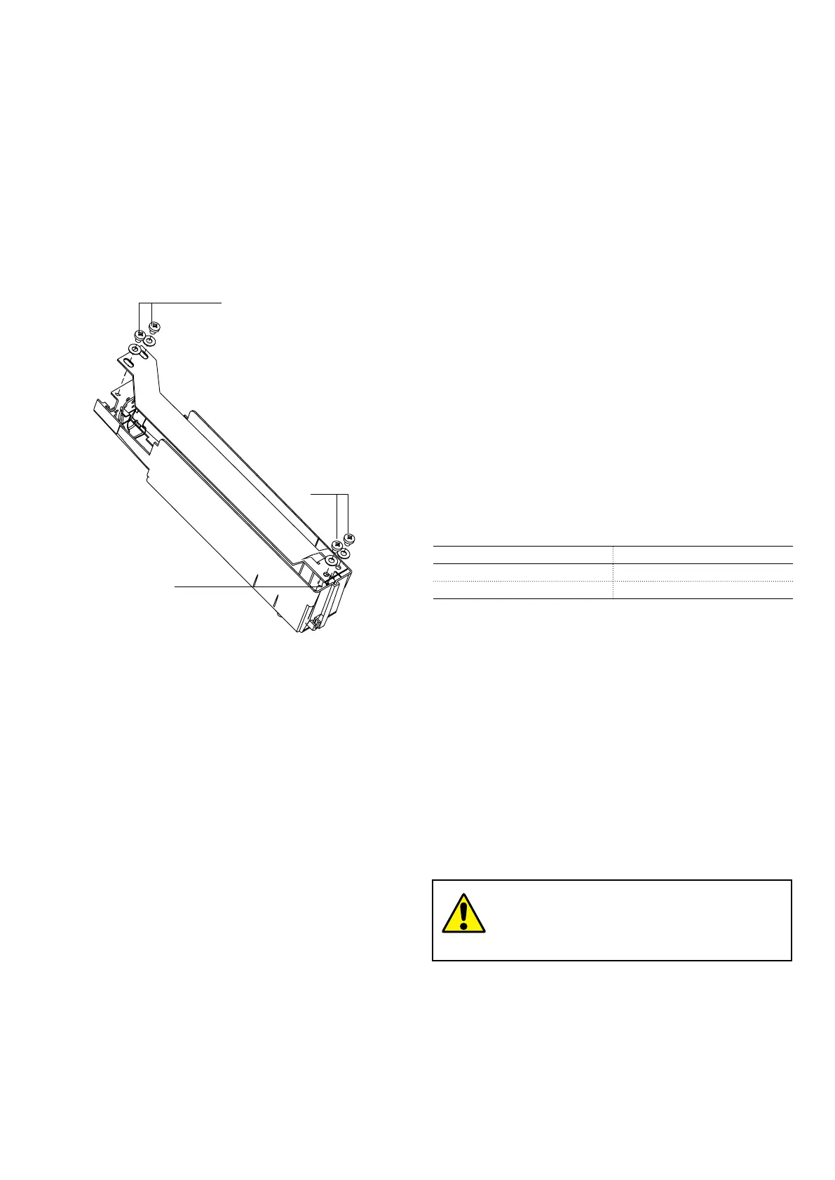
7.9. Mounting and dismantling the
short-circuit busbar
a) Mounting (fig. 21)
Mountthebusbarwiththefeelerpin(60)ontheoppositeside
tothatofthetulipsandfixitwiththescrews(61).
b) Dismantling (fig. 21)
Todismantle,proceedinreverseorder.
The same instructions are given in the Kit sheet put in the
short-circuit busbar packing.
NEPSI.COM - Northeast Power Systems. Inc.

 Loading...


