42
54
55
58
51
52
53
32
61
61
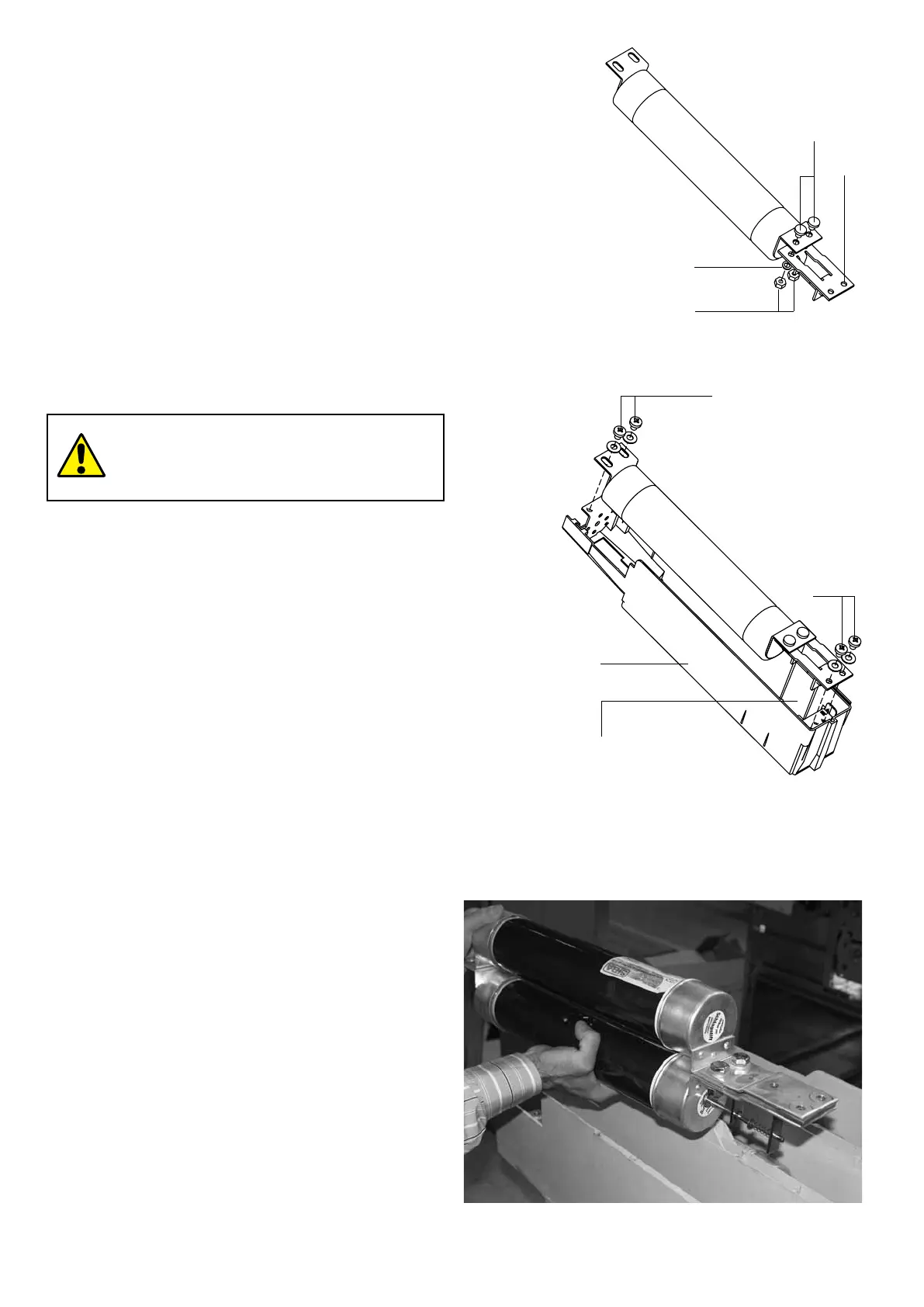
Fig. 20a
Fig. 20b
a) Mounting the adapters (fig. 20a)
Thefuseholder(32)(fig.20b)ispresettotakefuseswithfixing
centredistanceof553mm.Forsmallersizes,threeadapters
areneeded,asindicatedbelow:
– adapter(51)forfuseswithfixingcentredistance
l = 235 mm
– adapter(52)forfuseswithfixingcentredistance
l = 305 mm
– adapter(53)forfuseswithfixingcentredistance
l = 454 mm.
Selectthetypeofadapter,fixitontothefuseonthestriker
sidebymeansofthegrubscrews(54),thecupsprings(55)
andtheshortnuts(58).Mounttheadapterwiththeextension,
with the cap facing the striker.
The same instructions are given in the Kit sheet put in the
adapter packing.
Only position the grub screws (54) as shown
in the drawing.
b) Mounting the fuses (fig. 20b)
Mountthefusesortheadapter(preassembledasindicated
inpar.a)withthestriker,(indicatedbythearrow)facingthe
opposite side to the one of the contactor tulips and fix them
bymeansofthescrews(56)andthespringwashers(57).
c) Dismantling the fuses
Todismantlethefusesandrelativeadapters,proceedin
reverse order to par. b) and a).
d) Assembling and dismantling the VSC/PN and VSC/PNG
contactor fuses
It is also possible to use BS fuses with double cartridge
connected in parallel in the VSC/PN and VSC/PNG contactors
(fig.20c)andthereforeinserieswiththecontactor.The
assembly and dismantling operations are the same as what
isdescribedinsectionsa),b)andc)above,withtheonly
difference being to handle a pair of fuses per phase at the
sametime(fig.20c)connectedbymeansofasuitable
adapter.
Striker side
Fig. 20c
NEPSI.COM - Northeast Power Systems. Inc.

 Loading...


