23
Cabling
Makeshortconnections(maximum1metre)insidethe
medium voltage units and avoid positioning them close to the
medium voltage busbars.
All long connections must follow paths as close as possible to
the metallic frame. The connections must also be fitted with
ferrite rings to suppress high frequency interference.
It is good practice to run the cables inside metallic pipes or
ducts(earthedatseveralpoints)whentheyaresubjecttoor
may be a cause of interference.
Cabling and earthing procedures according to IEC 61000-
5-2 Standards: “Technical report: Installation and mitigation
guidelines”.
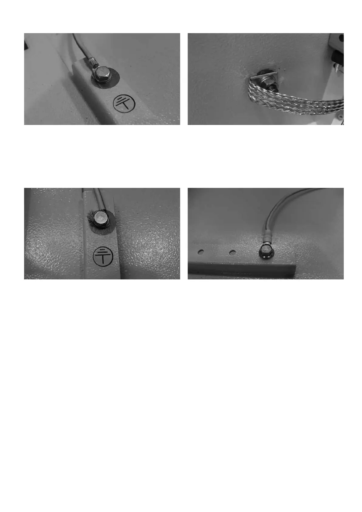
Fig. 8a Fig. 8b
Fig. 8c Fig. 8d
Figs. 8a - 8b show a grounding operation carried out correctly.
Figs. 8c - 8d show a grounding operation not carried out correctly and which, apart from being dangerous, does not
guarantee correct operation of the VSC.
Wherepossible,thepowersupplyandauxiliarycircuit
cables must be braided. Their length must be calculated
appropriately to prevent any surplus and the maximum length
must be:
•135mfor24to130Vauxiliaryvoltage
•400mfor220to250Vauxiliaryvoltage
Longer lengths require an additional filter for every operating
inputused(consultABB).
Inanycase,anysurpluspartsofcablesmustbewound
separately and taken into the low voltage apparatus
compartment. Always avoid placing them in the vicinity of the
medium voltage cables or close to cables which may generate
interferenceordisturbances,suchascurrentorvoltage
transformer cables or power supply cables.
NEPSI.COM - Northeast Power Systems. Inc.

 Loading...


