32
• ThisoperationmustbecarriedoutbyABBpersonnelor
by suitably qualified customer personnel with in-depth
knowledgeoftheapparatus(IEC62271-1,par.10.4.2.).
• Alwayscheckthattheapparatusisintheopenposition
before carrying out any activities.
Check that the medium voltage and auxiliary power supplies
have been removed.
Maintenance of the apparatus must only be carried out with
thecontactorde-energized,racked-outofthecompartment
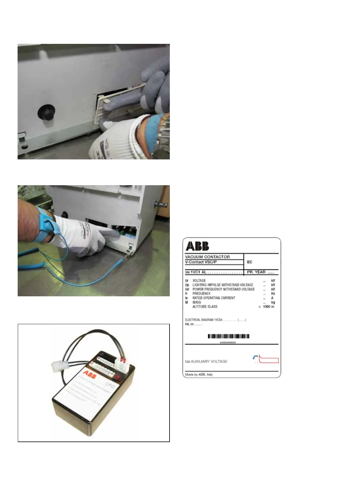
of the enclosure and with the capacitor of the auxiliary
circuitdischarged.Todischargethecapacitor,remove
power from the -XDB10 terminal box and connect the
mobile two-pole -XDB50 connector to the ABB type CFD
device(fig.13c).Completionofdischargingissignalledby
the red light going completely off.
• Theauxiliarycircuitcanbeconfiguredforallthedirectand
alternating current voltages within the reference range. To
changethevoltagevaluedefinedduringtheorderingstage,
proceed as follows: 1) remove the rear plastic protection
(fig.13a);2)accesstheMACR2electroniccard(fig.13b);
3) prepare the dip-switches according to the indications
given on the last page of the electric circuit diagram.
• Afterhavingsetthedesiredvalue,thelabelwiththenew
voltage value must be overlayed the front rating plate of the
contactor.
Fig. 13a
Fig. 13b
Fig. 13c
Fig. 13d
• Thesmallplatewiththecorrectvoltagevalueisinthe
documentenvelopeaccompanyingtheproduct,alongwith
the electric circuit diagram and this manual.
• Contactorfunctionalcheckismandatoryafterthenew
voltagesetting;thequalifiedcustomer’spersonnelshould
carryoutthischeck,responsibilityfortheinterventionslies
with the customer.
5.7.2.1 Changing the supply voltage of the contactor
(within the reference range)
NEPSI.COM - Northeast Power Systems. Inc.

 Loading...


