MEDIUM VOLTAGE PRODUCTS
25
Make sure that the circuit breaker is open
and the closing springs discharged before
removing the operating mechanism cover to
access the terminal box.
Table2
Bolt
Recommended tightening torque
(
)
Without lubricant With lubricant
(
)
(
1
)
The nominal tightening torque is based on a 0.14 friction coefficient of the
thread (distributed value to which the thread is subjected and which, in
some cases, is not negligible).
The nominal tightening torque with lubricant complies with DIN 43673
Standards.
(
2
)
Oil or grease. Thread and surfaces in contact with the lubricated heads.
Consider the deviations from the general Standards table (for example,
for systems in contact or terminals) as established in the specific
technical documentation.
The thread and surfaces in contact with the heads of bolts must be
slightly oiled or greased, so as to obtain a correct nominal tightening
torque.
Assembly procedures
Place the connections in contact with the circuit
breaker terminals.
Insert a spring washer and a flat washer
between the head of the bolt and the
connection.
The diameter of the flat washers must be able to
distribute the torquing pressure over a wide
area.
Tighten the bolt, taking care to prevent the
insulating parts from being stressed. Use of DIN
class 8.8 standard bolts is recommended, also
with reference to the indications in table 2.
Make sure that the connections do not exert any
force on the terminals.
Carefully comply with the manufacturer’s
instructions for terminating the cables in cable
connections.
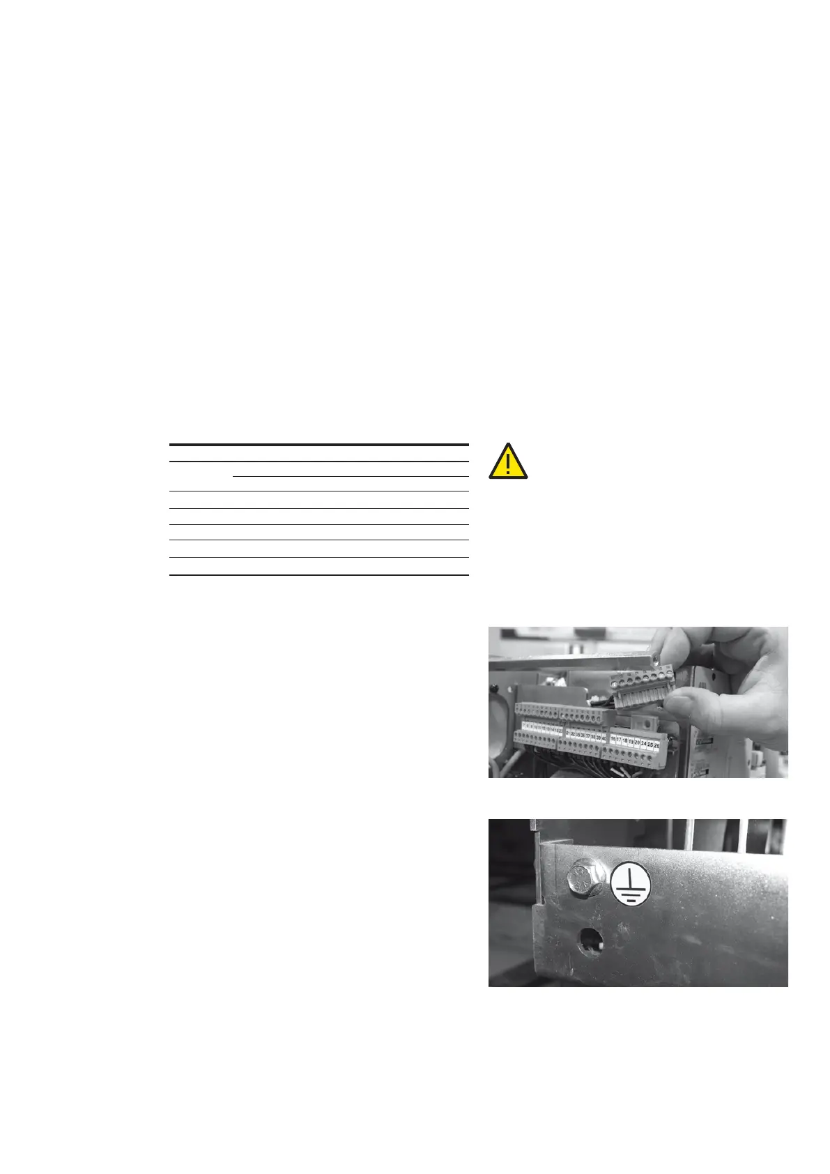
7.7 Earthing
Earth fixed version circuit breakers by means
of the special screw marked with the relative
symbol. Clean and degrease the area around
the screw corresponding to a diameter of about
30 mm. Use a conductor (busbar or cord) with a
cross-section conforming to the Standards in
force.
When the assembly is completed, cover the joint
with vaseline grease.
7.8 Connection of the auxiliary
circuits
The minimum cross-section of the wires used for
the auxiliary circuits must not be less than the one
used for the internal cabling.
Furthermore, they must be insulated for a 2 kV
test voltage at power frequency according to
standard IEC 60694 sect. 6.2.10.
7.8.1 Fixed version circuit breakers
The auxiliary circuits of the circuit breaker must
be connected by means of modular terminals
installed under the cover.
The wires outside the circuit breaker must be
routed inside appropriately earthed metal tubes
or ducts.
7.8.2 Circuit breakers for ABB switchgear
The auxiliary circuits are fully wired in the factory
through to the connector. Please refer to the
wiring diagram of the switchgear for the
connections.
Figure 10
Figure 9