2. Create the pocket so that the generator is parallel to the skin surface. Ensure the pocket is at least2.
0.5 cm (0.20 in.) below the surface of the skin but does not exceed a depth of 2.5 cm (0.98 in.).
3. Insert and remove the pocket sizer to ensure that the pocket is large enough to accommodate the3.
generator, allowing enough extra room for a strain relief loop for each lead or extension.
Connecng a Lead or Extension to the Generator
The following steps outline the suggested guidelines to connect a lead or extension to the generator:
WARNING: To avoid harming the paent or damaging the neurosmulaon system, ensure that any
electrosurgery procedures are completed before connecng the leads or extensions to the generator.
CAUTION: Do not connect a lead or extension with body uid or saline residue on its contacts because
corrosion can occur and cause failure of the system.
1. If any of the lead or extension contacts are exposed to body uid or saline, thoroughly clean the1.
contacts with sterile deionized water or sterile water for irrigaon and dry them completely.
2.
To help ensure that the lead or extension can be fully inserted into the generator header, insert the
2.
torque wrench through the septum on the generator header, turn the torque wrench clockwise to
ghten the setscrew unl the torque wrench clicks, and then loosen the setscrew again by turning the
wrench counterclockwise about 2.5 mes.
CAUTION: Use only the torque wrench included in the extension, generator, or torque wrench kit. If
you need to loosen the setscrew, turn the setscrew (in quarter turns counterclockwise) just enough
to insert or remove the lead or extension from the generator header. Retracng the setscrew too
far may cause it to come loose and fail to secure the lead or extension to the generator.
CAUTION: To avoid sharply bending and damaging the lead or extension when performing the
following step, insert the lead or extension parallel with the header port. Addionally, try grasping
the lead or extension about 5 mm at a me from the opening of the header port while inserng.
3.
Using clean gloves, carefully slide the proximal end of the lead or extension into the generator header
3.
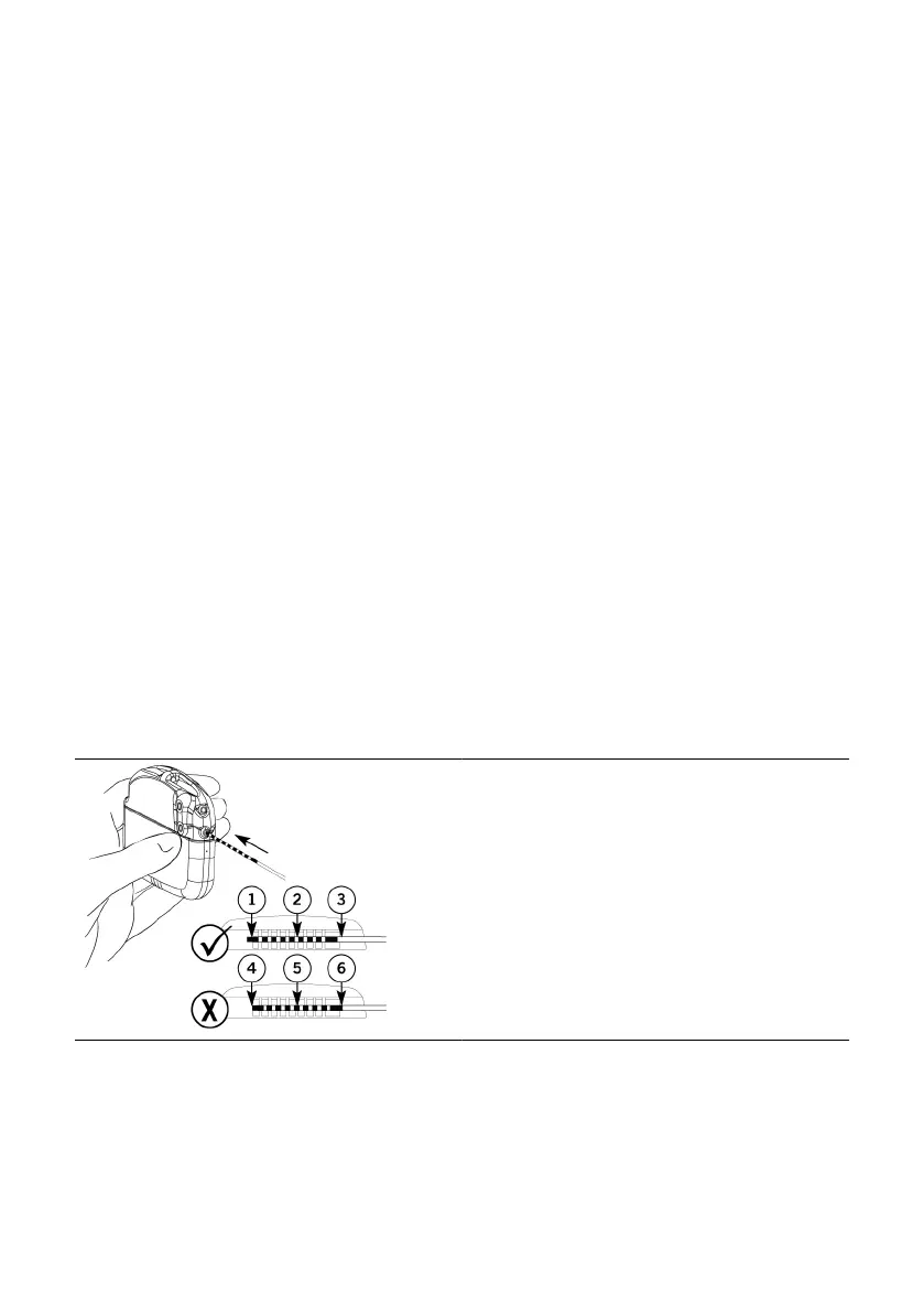
unl it stops. Conrm that the lead or extension is correctly inserted by following these visual indicators
and referring to the following gure:
–
The rst contact band (at the p) of the lead or extension extends slightly past the rst header
–
contact and is visible, the windows between each of the header contacts are clear, and the ninth
contact band of the lead or extension is not visible.
Figure 3. Correct versus incorrect inseron of the lead or extension
Fully inserted
1. First contact band (p) is visible past the rst1.
header contact
2. Window between each header contact is clear2.
3. Ninth contact band is not visible3.
Not fully inserted
4. First contact band (p) is not visible past the rst4.
header contact
5. Window between each header contact is5.
parally blocked by contact band
6. Ninth contact band is visible6.
4. Use the clinician programmer app to communicate with the generator and test the impedance to4.
ensure that the lead or extension is fully inserted. See the clinician's manual for the clinician
programmer app for instrucons.
NOTE: To test the system integrity turn o Surgery mode. Aer system integrity has been veried, set
the generator back into Surgery mode before closing the pocket.
NOTE: If the system integrity check fails, disconnect the lead or extension and reconnect to the
generator. Repeat the system integrity check.
8
–