2000 advanced/2000 13 Appendix
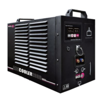
Figure 16 Open the connection housing
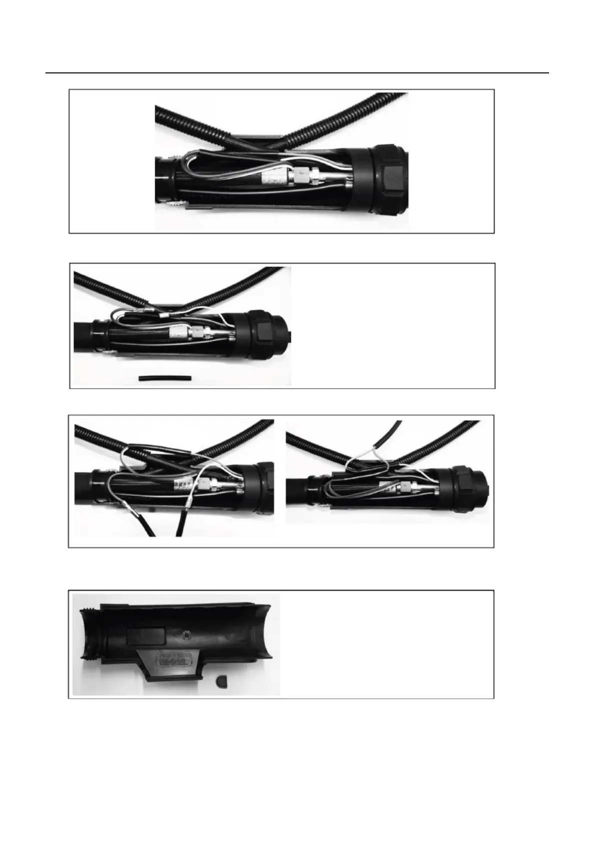
Figure 17 Disassemble a trigger cable
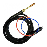
Figure 18 Connect the trigger cable to the flow monitor cable
Install the shrink hose for insulation
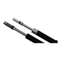
Figure 19 Remove the seal cover and use the opening on the housing as a control line outlet
EN - 26