13 Appendix 2000 advanced/2000
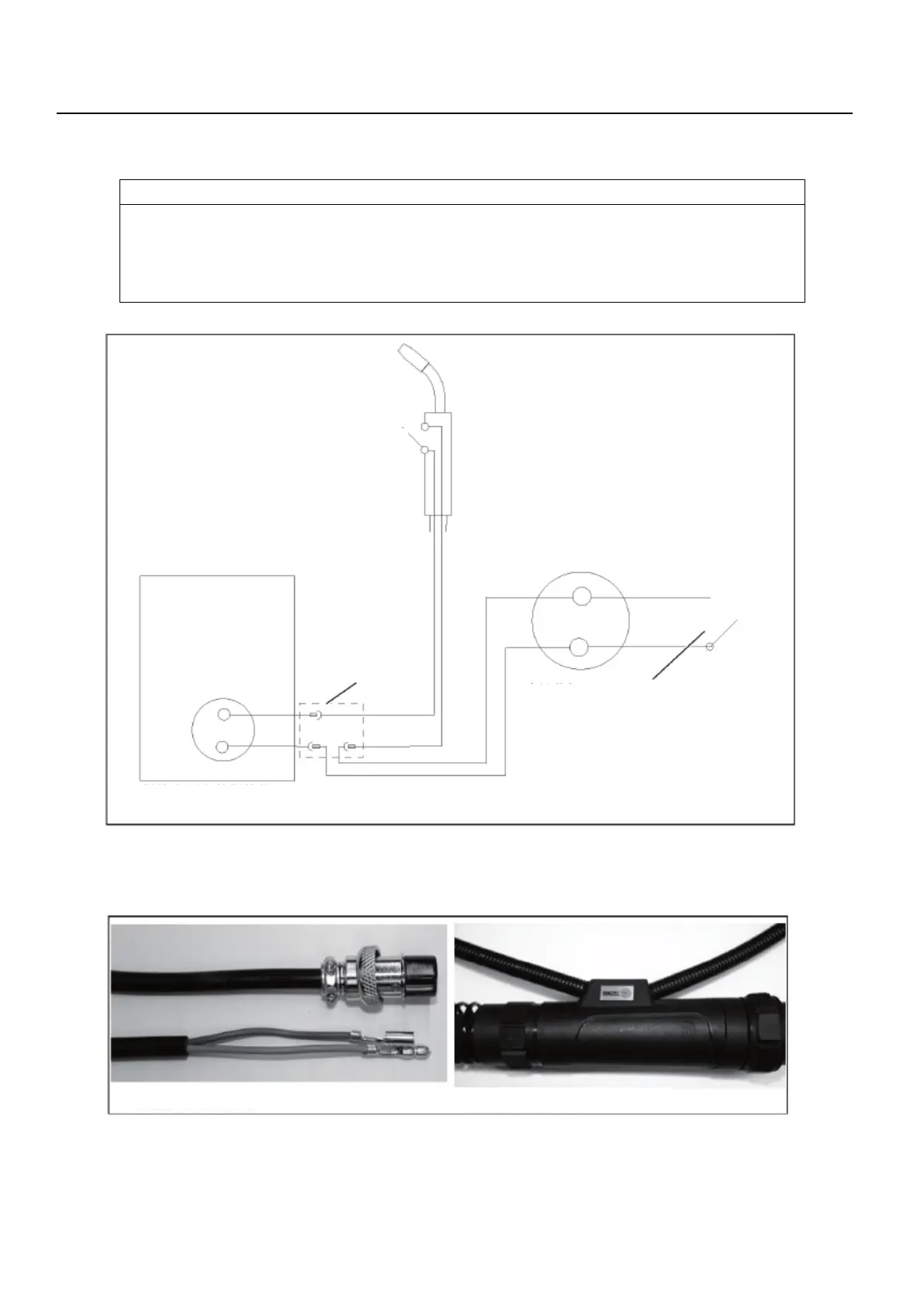
13.3 Connecting diagram of the flow monitor (applicable to model 2000)
NOTICE
• This connecting diagram is only suitable for the two-cycle mode.
• When the coolant level is low, the cooling unit disconnects the welding current if and the torch
trigger is pressed.
• The flow monitor is preset to 0.6 – 0.8 l/min.
Figure 14 Connecting diagram of the flow monitor
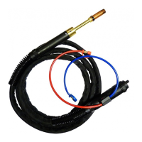
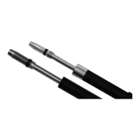
13.3.1 Flow monitor assembly instructions (applicable to model 2000)
Figure 15 Initial state
EN - 25
power source
housing
the welding power source
Flow monitor connector in the
front of the cooling unit
Flow monitor (The switch turns on
when the coolant flow rate is low)
2 Machine-side connection housing
1 Flow monitor control line