Hardware Setup
IP35/IP35-E 1-7
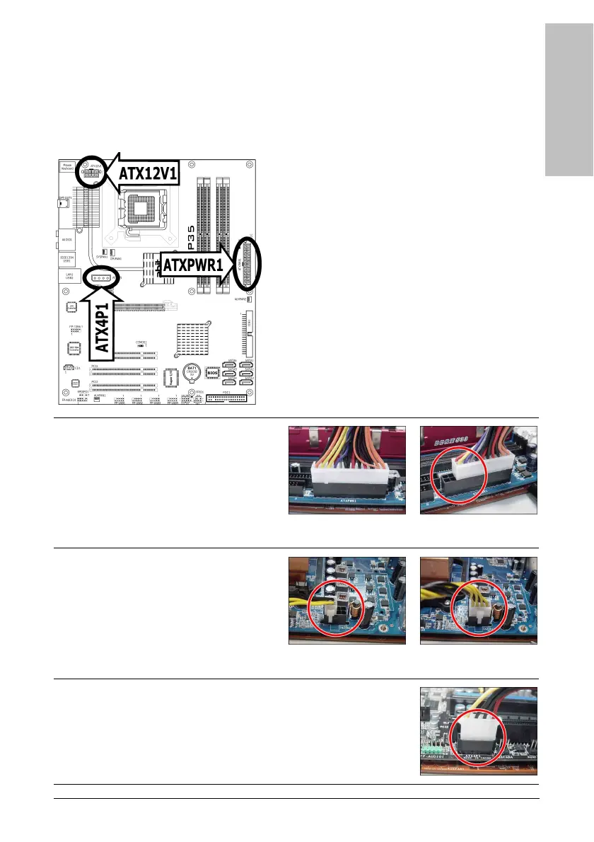
1.6 Connecting Chassis Components
1.6.1 ATX Power Connectors
These connectors provide the connection from an ATX12V power supply. As the plugs from the
power supply fit in only one orientation, find the correct one and push firmly down into these
foolproof-designed connectors.
For a fully configured system, we recommend that
you use a power supply of ATX12V 2.0 (or newer)
specification compliant and of providing minimum
400W power output capability.
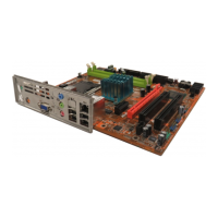
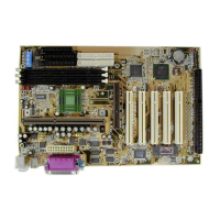
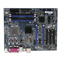
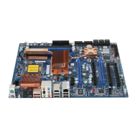
※ The following motherboard photos are
served for DEMO only, and may not be
the same type or model as the one
described in this user’s manual.
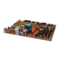
[ATXPWR1]: 24-pin power connector
You may connect either a 20-pin (ATX12V
1.3) or 24-pin (ATX12V 2.0) power source.
However, it is recommended to connect the
24-pin ATX12V power source to meet the
240VA protection limits.
Plugged from a 24-pin
ATX12V power.
Plugged from a 20-pin
ATX12V power.
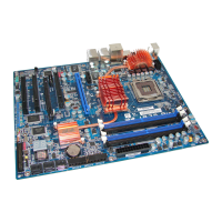
[ATX12V1]: 8-pin power connector
This connector supplies +12V power to CPU.
You may connect either a 4-pin ATX12V or
an 8-pin EPS12V power source. However, it
is recommended to connect the 8-pin
EPS12V power source to meet the 240VA
protection limits.
Plugged from a 4-pin
ATX12V power.
Plugged from an 8-pin
EPS12V power.
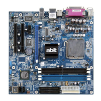
[ATX4P1]: Auxiliary 12V power connector
This connector provides an auxiliary power source for devices added
on PCI Express slots.