www.accuenergy.com
V: 1.0 Revised: Jan. 2018
Chapter 3: Installation - Conguration Parameter Set-up
35
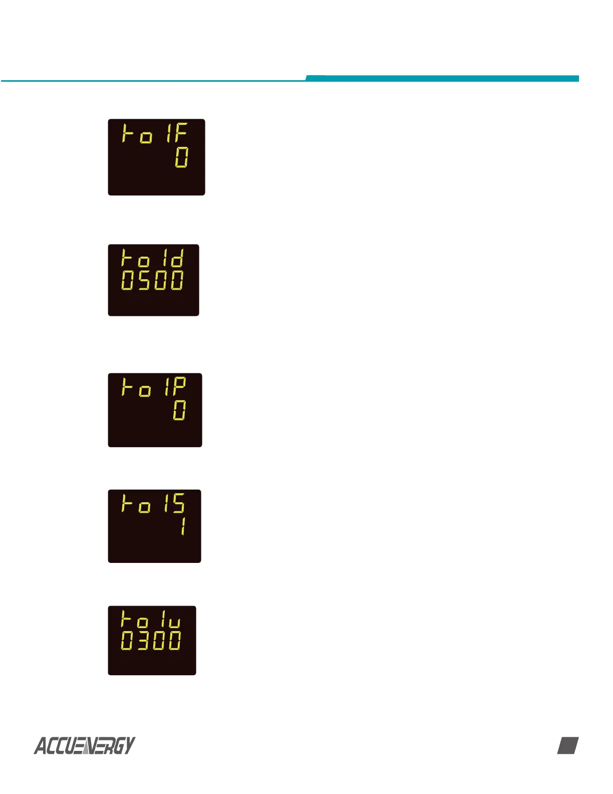
RO1 mode setting: In the parameter setting mode, hold ‘V/A’ for 3
seconds until the screen ‘Ro1F’ displays (as shown in Fig 3-23), the
meter is in RO parameter setting mode. There are 3 RO1 modes:
0: Latch; 1: Momentary; 2: Alarm. Press ‘F’ key to select the mode
number (0, 1 or 2), and then press ‘V/A’ key to confirm and scroll
to the next screen setting page. For example, Fig 3-25 shows the
RO1 mode is Latch.
RO1 momentary delay time setting: In RO parameter setting
mode, if RO1 mode is set as 1, Momentary, press ‘V/A’ key until the
screen ‘Ro1d’ displays. The delay range in 300 ~ 5000 ms. Press
‘F’ to set the delay time. And then press ‘V/A’ key to confirm and
scroll to the next screen setting page. Fig 3-26 shows the RO1
momentary delay time is 500ms, or 0.5s.
RO1 alarm parameter setting: In RO parameter setting mode, if
RO1 mode is set as 2, Alarm, press ‘V/A’ key until the screen ‘Ro1P’
displays. There are 4 options: 0: no alarm; 1: voltage; 2: current; 3:
power. Press ‘F’ to select setting and press ‘V/A’ key to confirm
and scroll to the next screen setting page. Fig 3-27 shows the RO1
alarm is ‘no alarm’.
RO1 alarm inequality setting: In RO parameter setting mode, if
RO1 mode is set as 2, Alarm, press ‘V/A’ key until the screen ‘Ro1S’
displays. There are 2 options: 0: smaller than; 1: larger than. Press
‘F’ to select and press ‘V/A’ key to confirm and scroll to the next
screen setting page.
RO1 alarm threshold range setting: In RO parameter setting
mode, if RO1 mode is set as 2, Alarm, press ‘V/A’ key until the
screen ‘Ro1u’ displays. The threshold setting range is the same as
measurement range. Voltage: 0 ~ 3000V; Current: 0 ~ 50000A;
Power: 0- 60000kW. Press ‘F’ to edit the value, and press ‘V/A’ key
to confirm and scroll to the next screen setting page.
Fig 3-25 RO1 Mode
Setting
Fig 3-26 RO1
Momentary Delay
Time
Fig 3-27 RO1 Alarm
Parameter Setting
Fig 3-28 RO1 Alarm
Inequality Setting
Fig 3-29 RO1 Alarm
Threshold Range
Setting
SET
SET
SET
SET
SET

 Loading...


